Single Lumen Microcatheter for Executing Plugs near Distal Terminus of Lumen

Active Publication Date: 2018-08-16
WALZMAN INNOVATIONS LLC
View PDF4 Cites 3 Cited by
  • Summary
  • Abstract
  • Description
  • Claims
  • Application Information

AI Technical Summary

Benefits of technology

The invention is about a device that makes it easier to create a plug or equivalent near the end of micro-catheters. This makes it easier to deliver viscous liquids and other embolic agents to targeted locations in the body, while preventing unwanted reflux. Different embodiments of the invention including a hydrogel coating or a small side hole in the catheter can be used to achieve this. Overall, the invention improves the process of creating plugs and delivering liquids through micro-catheters.

Problems solved by technology

However, most are designed to drain cerebrospinal fluid from the ventricular through a catheter that enters through a hole in the skull and would not be capable of injecting glue into an artery that enters through the femoral artery and is snaked up through blood vessels in the body.
However, they could not be used to inject something into an artery within the brain, or to provide a temporary arterial bypass.
If it were introduced directly into the artery through the brain it would undoubtedly cause a life threatening bleed in the brain.
These include difficulty forming a proximal “plug” before too much distal Onyx prevents a subsequent ejective distal “push”, too much reflux of Onyx along the micro-catheter, approaching a normal branch artery, necessitating aborting that injection for safety concerns.
Additionally, typically the plugging material, such Onyx 34, when in contact with blood that is not moving will then start to solidify in the tip of the micro-catheter, and can obstruct it.
An obstructed, distal penetration of the lesion being treated with the embolics agent is no longer possible
Said difficulties can result in liquid embolic failure to penetrate the target area, such as a fistula's nidus.

Method used


Image

  • Single Lumen Microcatheter for Executing Plugs near Distal Terminus of Lumen
  • Single Lumen Microcatheter for Executing Plugs near Distal Terminus of Lumen
  • Single Lumen Microcatheter for Executing Plugs near Distal Terminus of Lumen

Examples


second embodiment

[0040]A modification of the second embodiment uses a particular size / diameter and shape of a channel distal to the side hole that would allow passage of dimethyl sulfoxide (DMSO), and would allow passage of the less viscous embolic agent such as ONYX 18, but would not allow passage of Onyx 34 or the like.

third embodiment

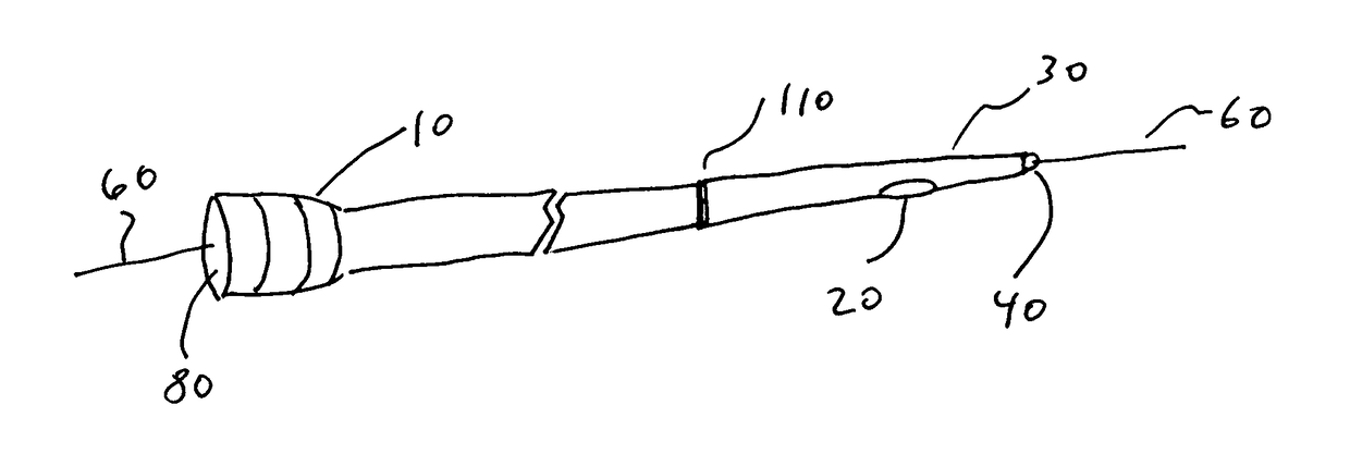
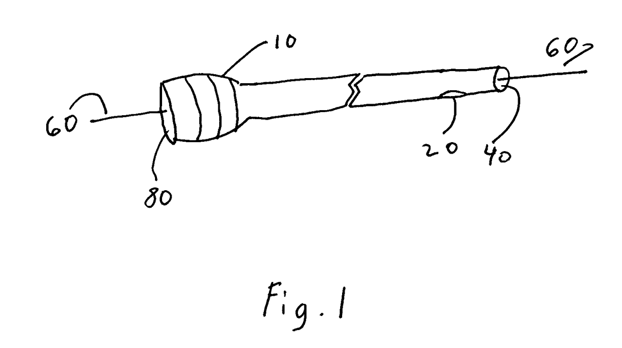
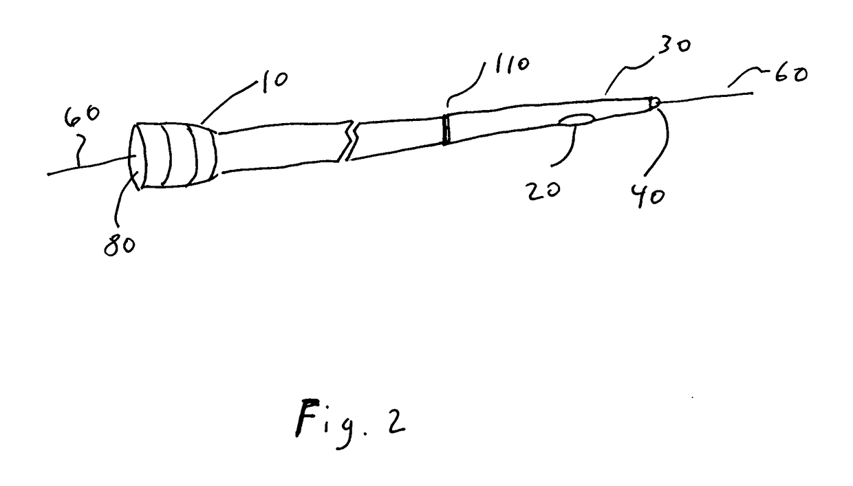
[0041]Referring now to FIG. 4, the present invention is composed of a catheter 10, a side hole 20, a distal end hole 40, a proximal catheter hole 80, and governing element 90. This embodiment a governing element 90 such as a flap valve, a “push” diaphragm, or other device capable of stopping Onyx flow from deploying out of the end hole 40 and thereby diverted to side hole 20. This embodiment incorporates the design of the Strata® valve, or other valve. Using a standard micro-catheter with a valve on the inner lumen of the micro-catheter at the distal end of the side hole, that can be closed by a magnetic field created by an electric current applied after infusion of dimethyl sulfoxide.

[0042]Said valve can be opened by removal of the electric current (after the Onyx 34 or similar is injected and an adequate proximal “plug” is created). In particular, said valve contains a magnet or other means inside the valve mechanism that allows the neurosurgeon to change the opening setting of th...


PUM


Abstract

Micro-catheters and embolic agents offer better results in endovascular treatment of brain arteriovenous malformations. Using said micro-catheters and embolic agents generally requires the creating of a plug at the distal-most portion of said micro-catheters which regularly results in suboptimal results. The present invention teaches how to create and use a device which creates a plug downstream of the distal-most portion of said micro-catheters and thereby ameliorates the suboptimal outcomes associated with creating a plug at the distal-most portion of said micro-catheters.

Description

CROSS-REFERENCES[0001]This utility patent application claims the benefit of the priority date of provisional application Ser. No. 62 / 600,137 filed Feb. 13, 2017 (13-Feb.-2017).FEDERALLY FUNDED R&D[0002]NoneBACKGROUND OF THE INVENTIONField of the Invention[0003]This invention relates in general to medical equipment and procedures. In particular, the invention relates to catheters for use in performing certain medical procedures, such as the treatment of brain arteriovenous malformations includes endovascular embolization, surgical resection, and stereotactic radiotherapy, alone or in combination.[0004]The present invention is a tool to more safely and more effectively implement endovascular treatment of arteriovenous malformations and arteriovenous fistulas, reducing procedural times and exposure to X-ray radiation to the patient and the treating staff.Background Art[0005]Treatment of brain arteriovenous malformations includes endovascular embolization, surgical resection, and stereo...

Claims


Application Information

Patent Timeline
IPC IPC(8): A61B17/12A61M25/00
CPCA61B17/12181A61B17/12109A61M25/007A61M25/0021A61M25/0075A61M2025/0042A61M2205/0266A61B2017/1205A61M2025/0079A61B17/12186A61B17/1219A61B2017/00898A61B2090/037A61M25/0023A61M25/0074A61M2025/0188A61B2017/00938A61B2017/00473A61B17/12159
Inventor WALZMAN, DANIEL E.
Owner WALZMAN INNOVATIONS LLC
Why Eureka
Try Eureka