
Total knee replacement prosthesis assembly

a total knee replacement and prosthesis technology, applied in the field of total knee replacement prosthesis assembly, can solve the problems of limited application and clinical function of all the parts, and achieve the effect of preventing articulation

Active Publication Date: 2018-07-26
FITZBIONICS
View PDF2 Cites 0 Cited by
  • Summary
  • Abstract
  • Description
  • Claims
  • Application Information

AI Technical Summary

Benefits of technology

The invention is a total knee replacement prosthesis assembly that includes a femoral component, a tibial component, and a bearing component. The bearing component has a superior side with a convex outer bearing surface and a concave bearing surface of the femoral component that match to create a bicondylar joint. The assembly also includes an axle that is hingedly connected to the femoral and tibial components, providing a fixed axis of rotation. The axle has two axle side portions that engage with the bearing component to create a rotating platform. The assembly also includes a transverse bore in the bearing component that receives the axle and has guide surfaces for engagement with the axle side members. The technical effects of this invention include improved stability and reduced dislocation of the articulation, as well as improved range of motion and reduced wear on the bearing components.

Problems solved by technology

This is not true for the treatment of canine or feline populations where in the majority of cases euthanasia is usually a solution and for a few where there are a limited number of designs in the market that are available, these all have a very limited application and clinical function.
Component dislocation due to distraction is prevented only by the restraint of the soft-tissue envelope and dislocation is a potential problem with this knee replacement design.

Method used


Image

  • Total knee replacement prosthesis assembly
  • Total knee replacement prosthesis assembly
  • Total knee replacement prosthesis assembly

Examples


Embodiment Construction

[0040]The present embodiments represent currently the best ways known to the applicant of putting the invention into practice. But they are not the only ways in which this can be achieved. They are illustrated, and they will now be described, by way of example only.

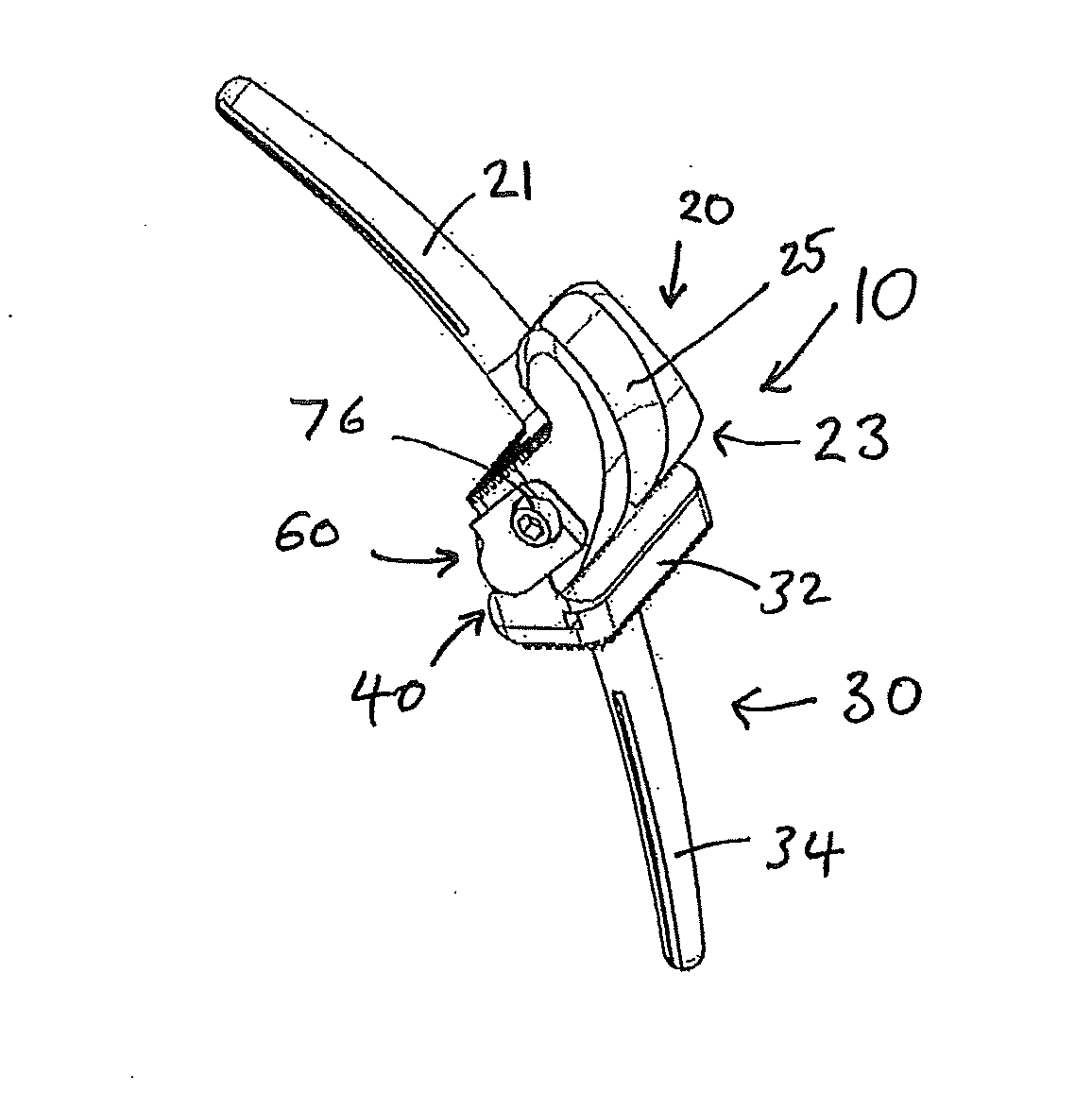
[0041]Referring to FIGS. 1 to 6, a total knee replacement prosthesis assembly 10 is shown for replacing a knee joint. The assembly shown in FIGS. 1 to 6 is suitable for replacing a left knee joint in a quadruped, however it will be understood that the features are also suitable for an assembly for implantation in a knee joint in a biped and that the features can be incorporated into a right knee joint replacement assembly.

[0042]The assembly 10 includes a femoral component 20, a tibial component 30, a bearing component 40 and an axle 60. The femoral component has a femoral stem 21 adapted to be received by an intramedullary canal of a femur and a distal portion 23 at the distal end of the femoral stem 21, configured to art...


PUM


Abstract

A total knee replacement prosthesis assembly (10) comprising a femoral component (20), a tibial component (30) having a tibial platform (32), and a bearing component (40), the bearing component having an inferior side (40b) and a superior side (40a), the bearing component being adapted to be arranged between the femoral component and tibial platform when assembled, the tibial platform having a post (36) upstanding from it and the bearing component having a post recess (46) in its inferior side for receiving the post, the bearing component being rotatable about the post when assembled, the post and bearing component each having a transverse bore and the assembly further comprising an axle (60), at least part of the axle being received through the transverse bore (38) in the post when assembled and at least part of the axle being received through the transverse bore (52) in the bearing component when assembled, the axle being configured to provide an axis of rotation between the femoral component and bearing component which is fixed relative to the femoral component and the bearing component in use.

Description

CROSS REFERENCE TO RELATED APPLICATIONS[0001]The present application is the U.S. national stage application of International Application PCT / GB2016 / 052197, filed Jul. 20, 2016, which international application was published on Jan. 26, 2017 as International Publication WO 2017 / 013428 A1. The International Application claims priority to Great Britain Application 1512696.4, filed Jul. 20, 2015.FIELD OF THE INVENTION[0002]The invention relates to a total knee replacement (TKR) prosthesis assembly for replacement of a knee joint.BACKGROUND TO THE INVENTION[0003]The knee joint is made up of the distal end of the femur, which articulates with the proximal end of the tibia, and the patella, which slides in a groove on the femur. Ligaments attach the femur and tibia to provide stability.[0004]The tibiofemoral joint at the knee in humans and animals allows for flexion (bending movement that decreases the angle between the femur and tibia) and extension (straightening movement). In addition to...

Claims


Application Information

Patent Timeline
IPC IPC(8): A61F2/38
CPCA61F2/3845A61F2/389A61F2/3859A61F2002/30364A61F2002/307A61F2/384A61F2002/30369A61F2/3868A61F2/3886A61F2/385
Inventor FITZPATRICK, NOELMESWANIA, JAYANTILAL
Owner FITZBIONICS
Learn More