
System, Control Method, and Control Terminal

a control method and control terminal technology, applied in the field of systems, control methods, and control terminals, can solve the problems of delay, complex selection or combination of connection methods, and lowering audio data quality, so as to reduce audio data quality, simplify control of each device, and lengthen audio cables

Active Publication Date: 2018-07-19
YAMAHA CORP
View PDF9 Cites 0 Cited by
  • Summary
  • Abstract
  • Description
  • Claims
  • Application Information

AI Technical Summary

Benefits of technology

The invention relates to a control terminal that can select one of multiple devices for receiving audio data via a network using an audio cable. The device selects the recipient based on the state of connection between the devices. The technical effect is the improved efficiency and ease of transmission of audio data using a network.

Problems solved by technology

In the case where the system is network-connected, a communication band of the network becomes insufficient depending on the data amount of audio data when the audio data is simultaneously transmitted to the plurality of reproduction devices, and therefore, for example the compression of audio data may be required.
When the audio data is compressed, there is a risk that the quality of audio data is lowered.
Moreover, when the audio data is transmitted via the network connection, a delay occurs.
However, the selection or combination of the connection methods is complicated, and there is a risk that the control of each device is complicated.

Method used


Image

  • System, Control Method, and Control Terminal
  • System, Control Method, and Control Terminal
  • System, Control Method, and Control Terminal

Examples


first embodiment

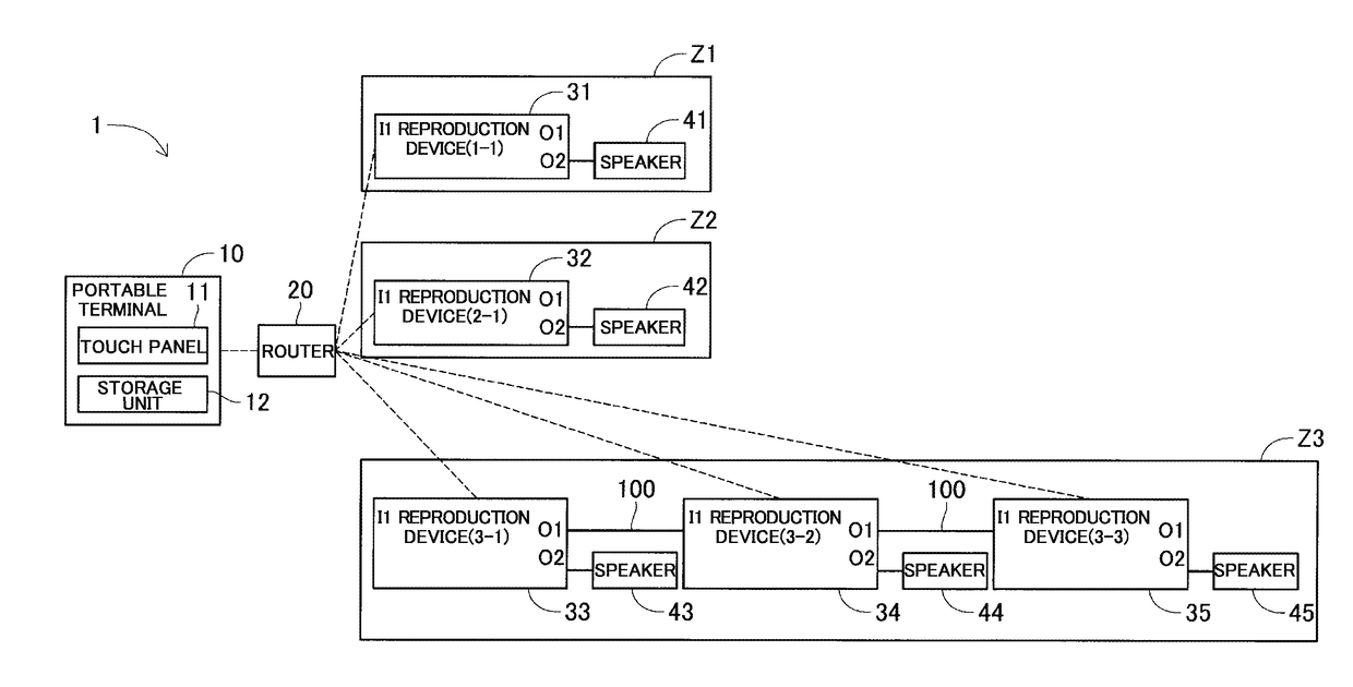
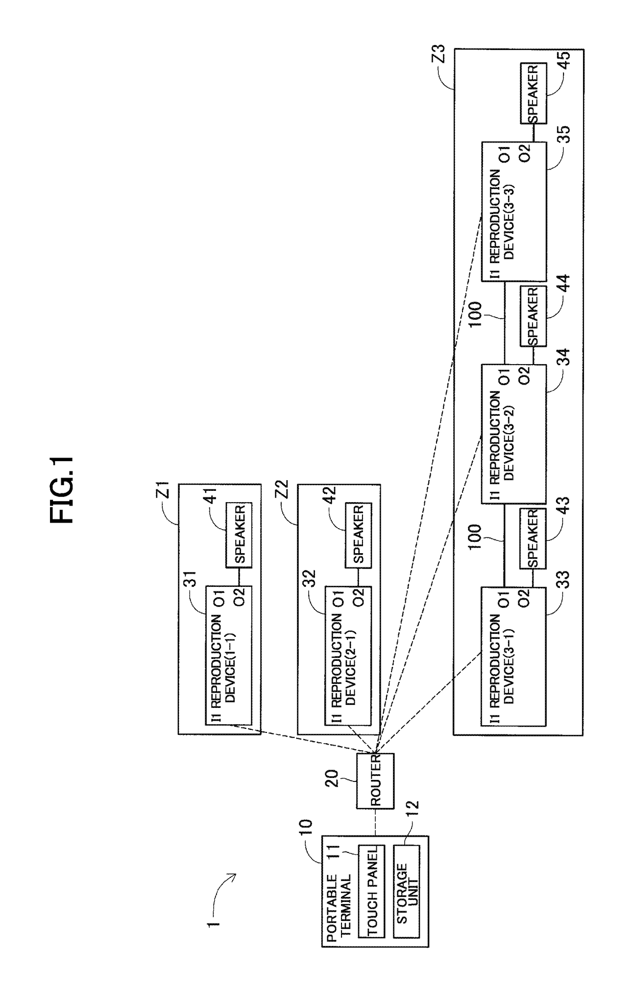
[0017]An overall configuration of a system 1 will be described using FIG. 1. The system 1 includes a portable terminal 10, a router 20, reproduction devices 31 to 35, and speakers 41 to 45. The portable terminal 10 and the reproduction devices 31 to 35 are connected to a local area network (LAN) via the router 20. The portable terminal 10 and the reproduction devices 31 to 35 have a wireless LAN function, and can perform wireless communication with each other. The reproduction device 31 is disposed in a zone Z1; the reproduction device 32 is disposed in a zone Z2; and the reproduction devices 33 to 35 are disposed in a zone Z3. Here, the zones Z1 to Z3 are respectively, for example, a kitchen, a children's room, and a living room. Each of the reproduction devices 31 to 35 includes an input terminal I1 and output terminals O1 and O2. The speakers 41 to 45 are respectively connected to the output terminals O2 of the reproduction devices 31 to 35. Moreover, regarding the reproduction ...

second embodiment

[0050] described as above, the following advantageous effects are provided.

[0051]By connecting the zones Z1 to Z3 by the audio cables 100, a configuration can be employed in which, in the reproduction devices 31 to 35 connected using the audio cables 100, audio data is transmitted via the wireless LAN to the reproduction device 31, and the audio data is transmitted via the audio cable 100 to the reproduction devices 32 to 35 to which the audio data is not transmitted via the wireless LAN, irrespective of the zones. According to this configuration, the number of reproduction devices to which the audio data is transmitted via the wireless LAN is made smaller than the number of reproduction devices included in the system 1, and the occurrence of communication band insufficiency of the network can be suppressed.

[0052]In the reproduction devices 31 to 35 connected using the audio cables 100, the reproduction devices 33 to 35 are disposed in the zone Z3. Therefore, after the audio data is...


PUM


Abstract

A plurality of reproduction sections are set. With regard to the reproduction section provided with the first reproduction device group that includes at least one reproduction device connected via a network with a storage that stores audio data, the audio data is transmitted via the network to each reproduction device. With regard to the reproduction section provided with the second reproduction device group includes a plurality of reproduction devices that are connected to each other using at least one audio cable and that include at least one reproduction device connected via the network with the storage, the audio data is transmitted via the network to at least one reproduction device connected via the network with the storage, and the at least one reproduction device is caused to transmit the received audio data via the at least one audio cable to at least one other reproduction device.

Description

CROSS-REFERENCE TO RELATED APPLICATION[0001]This application is a continuation of PCT International Application No. PCT / JP2016 / 083849, filed Nov. 15, 2016, which claims priority under 35 U.S.C. § 119 from Japanese Patent Application No. 2015-237616, filed Dec. 4, 2015, the entire disclosures of which are herein expressly incorporated by reference.BACKGROUND OF THE INVENTION1. Field of the Invention[0002]The present invention relates to a system, a control method, and a control terminal.2. Description of the Related Art[0003]A system including a plurality of reproduction apparatuses has been conventionally known. For example, JP 2008-92546 A discloses a communication system including an adapter provided with a means of extracting data corresponding to a channel to be reproduced from data to be reproduced and controlling reproduction timing.SUMMARY OF THE INVENTION[0004]Incidentally, there is a system having a so-called multi-zone function by which, when the system includes a pluralit...

Claims


Application Information

Patent Timeline
Patent Type & Authority Applications(United States)
IPC IPC(8): H04R3/12H04L12/28H04W8/00
CPCH04R3/12H04L12/2803H04W8/005H04L2012/2849H04R5/02H04R5/04H04R27/00H04S3/006H04R2205/024H04R2227/003H04R2227/005H04R2420/07
Inventor USUI, ATSUSHIKANO, MASAYA
Owner YAMAHA CORP
Learn More