Field hockey stick

a hockey stick and field hockey technology, applied in the field of field hockey sticks, can solve the problems of easy slippage, poor control of hockey balls, and difficult to receive hockey balls at the scoop of the head, and achieve the effects of effective hitting and/or guiding, flexible control, and optimal control

Inactive Publication Date: 2018-07-19
ADIDAS
View PDF12 Cites 0 Cited by
  • Summary
  • Abstract
  • Description
  • Claims
  • Application Information

AI Technical Summary

Benefits of technology

[0023]The back surface may comprise a plateau surface and two lateral surfaces connecting the plateau surface with the front surface. A width of the plateau surface may be smaller than a width of the front surface, such that the head has a trapezoidal cross-sectional shape. Such geometry provides a player with optimal control over the direction of the ball during lifting.
[0024]A distance between the front surface and the plateau surface may define a thickness of the head. The thickness tapers from a bend of the head towards a distal end of the head and towards a proximal portion of the head. Such geometry allows a player to flexibly and effectively hit and/or guide a hockey ball using different parts of the head. For example, a player can hit the hockey ball powerfully at the...

Problems solved by technology

This bend angle is normally relatively small, for example, about 30 degrees, which results in the drawback of poor control over a hockey ball.
With such a small bend angle, it is difficult to receive a hockey ball at the scoop of the head because only a small part of the circumference of the hockey ball can be received therein.
When ...

Method used


Image

  • Field hockey stick
  • Field hockey stick
  • Field hockey stick

Examples


Embodiment Construction

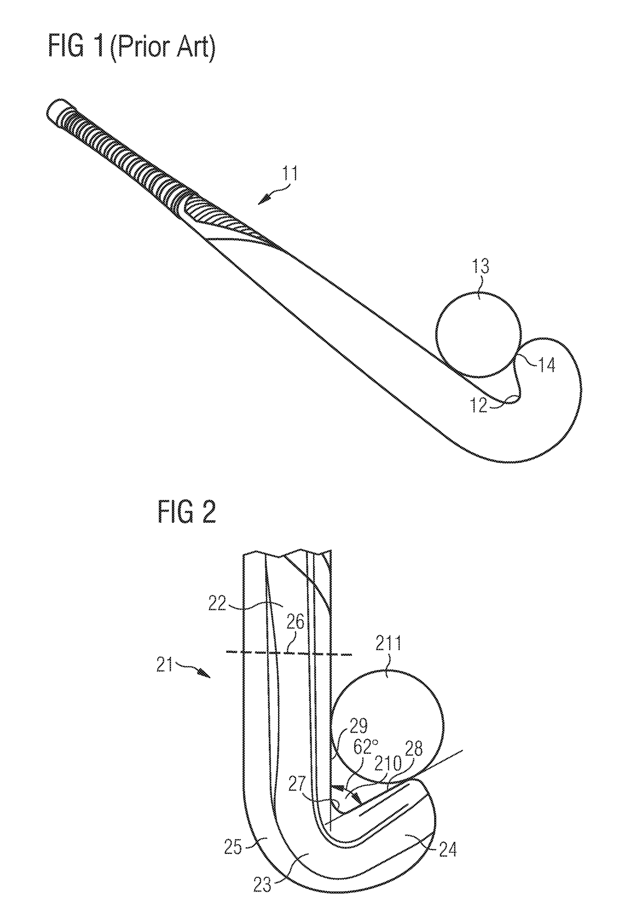
[0037]FIG. 2 shows a field hockey stick 21 according to a first aspect of some embodiments. The field hockey stick 21 comprises a shaft 22 and a head 23. The head 23 comprises a distal portion 24, a proximal portion 25 that is integral with a first end 26 of the shaft 22, and a bend 27 between the distal portion 24 and the proximal portion 25, such that an inner edge 28 of the distal portion 24 faces an inner edge 29 of the proximal portion 25. An angle of the bend 27 between the inner edge 28 of the distal portion 24 and the inner edge 29 of the proximal portion 25 is generally between 30 and 70 degrees. In some embodiments, as shown, for example, in FIG. 2, the bend angle 27 is 62°. In some embodiments, the bend angle 27 can be between 50° and 65°. Also, according to some embodiments, the inner edge 28 of the distal portion 24 is straight or concave. In some embodiments, as shown, for example, in FIG. 2, the inner edge 28 is straight.

[0038]The field hockey stick according to some ...


PUM


Abstract

A field hockey stick includes a shaft and a head. The head includes a distal portion, a proximal portion that is integral with a first end of the shaft, and a bend between the distal portion and the proximal portion, such that an inner edge of the distal portion faces an inner edge of the proximal portion. A bend angle between the inner edge of the distal portion and the inner edge of the proximal portion is between 30 and 70 degrees. The inner edge of the distal portion is straight or concave.

Description

BACKGROUNDTechnical Field[0001]The present disclosure relates to a field hockey stick.Background[0002]A field hockey stick comprises a handle and a head. By means of the handle, the stick is held by a player. The head is the part of a field hockey stick which comes into contact with a hockey ball and comprises generally a J or U shape. It is a general objective to provide to a player a hockey stick with maximum control over a hockey ball. Different attempts have been made to pursue this objective.[0003]For example, U.S. Pat. No. 4,512,573 relates to a hockey stick having a head attached to a handle in such a manner that the free end of the head is bent through 180° with regard to the handle. The hockey stick is formed from a plurality of laminations and the head has a portion which is thickened. The distance between the free end of the head and the handle is such that a hockey ball cannot pass through.[0004]U.S. Pat. No. 6,547,683 relates to a hockey stick having a head with an enla...

Claims


Application Information

Patent Timeline
IPC IPC(8): A63B59/70
CPCA63B59/70A63B2102/22A63B2209/00A63B2209/02
Inventor SINN, MICHAEL
Owner ADIDAS
Why Eureka
Try Eureka