Frame mounting after foil expansion

a technology of foil expansion and mounting, which is applied in the direction of fine working devices, electrical devices, semiconductor devices, etc., can solve the problems of limited reproducibility of such a process, and achieve the effect of avoiding wrinkles and bending, and ensuring the integrity of the wafer

Active Publication Date: 2018-07-05
INFINEON TECH AG
View PDF2 Cites 1 Cited by
  • Summary
  • Abstract
  • Description
  • Claims
  • Application Information

AI Technical Summary

Benefits of technology

[0037]In an embodiment, the workpiece, in particular wafer, has a size of more than 12 inch, in particular of at least 18 inch. As a result of the concept of expanding the foil prior to its mounting with frame and workpiece, in particular wafer, a spatially homogeneous and directionally radially outwardly oriented expansion force is conserved. This makes it possible to mount even workpieces, in particular wafers, with a large size without the risk of wrinkling, bending, or other artefacts of the foil. This allows processing also large wafers in a reliable and precise way. Also handling of very thin workpieces as part of the arrangement may be significantly simplified by the generation and conservation of the expansion force remaining to act on the foil when its assembly with the frame is completed.
[0038]In an embodiment of the arrangement, the integral workpiece is mounted on the expanded foil substantially without tensile stress. When the workpiece is mounted on the foil when the latter is already fully expanded and is fixed on...

Problems solved by technology

Conventionally, reproducibi...

Method used


Image

  • Frame mounting after foil expansion
  • Frame mounting after foil expansion
  • Frame mounting after foil expansion

Examples


Embodiment Construction

[0009]In the following, further exemplary embodiments of the apparatus, the method, and the arrangement will be explained.

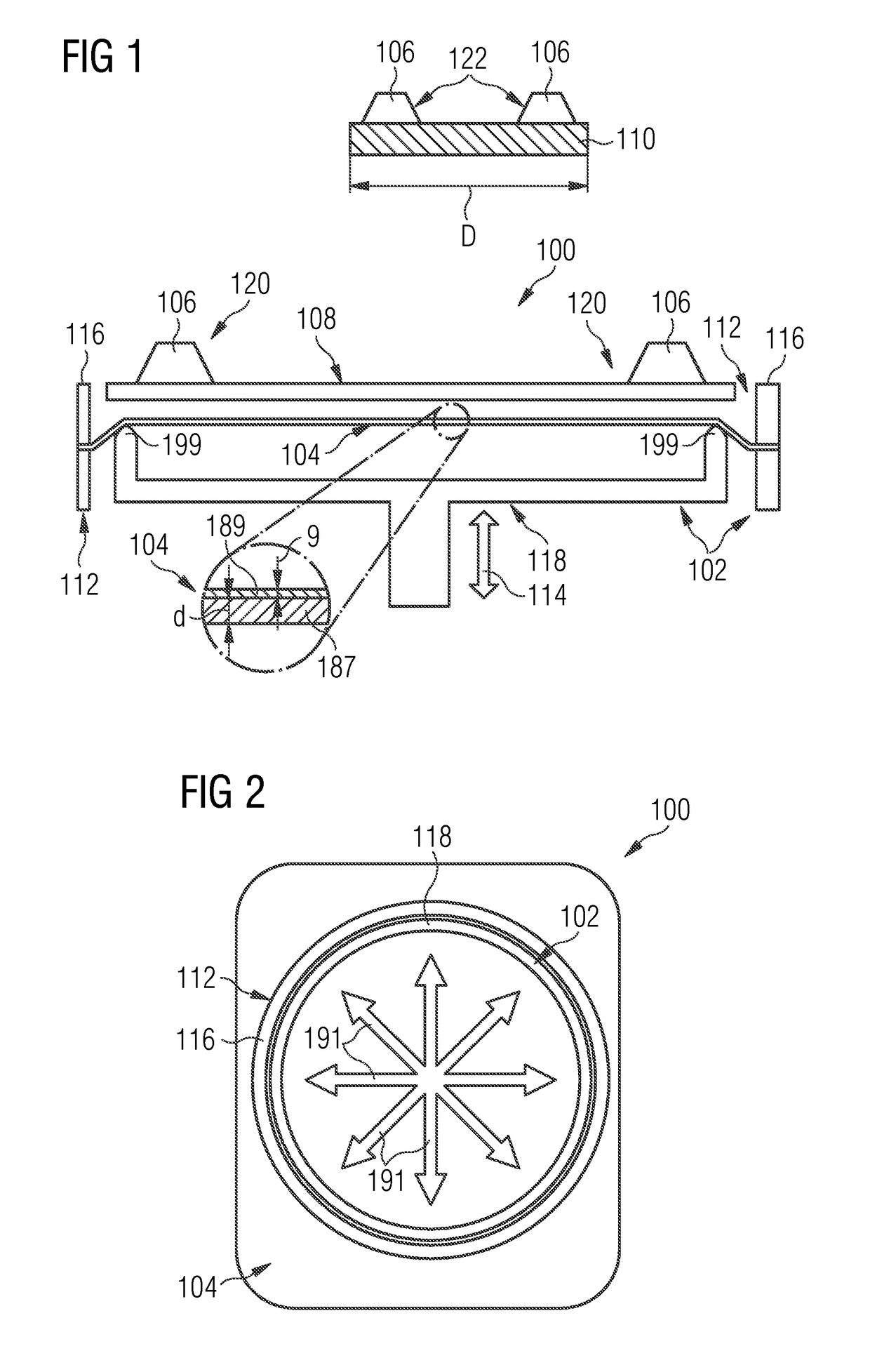
[0010]In the context of the present application, the term “radially symmetrically” may particularly denote a symmetry with respect to spatial directions corresponding to different or all radii of a virtual circle around a center and within the plane of the expanded foil. In particular, a radially outwardly directed force may act along the entire circumference of the expanded foil, in particular with a circumferentially identical absolute value of the force.

[0011]It should be appreciated that a skilled person is aware of the fact that foils (for instance as a result of their manufacturing process, for example by rolling) may have an intrinsic slightly asymmetric expansion characteristic. Without wishing to be bound to a specific theory, it is presently believed that a reason for the mentioned phenomenon is a slightly different cross-linking of polymers and a sligh...


PUM

PropertyMeasurementUnit
Sizeaaaaaaaaaa
Sizeaaaaaaaaaa
Forceaaaaaaaaaa

Abstract

An apparatus which comprises an expansion unit configured for expanding a foil, and a mounting unit configured for subsequently mounting the expanded foil on a frame and a workpiece, in particular a wafer, on the expanded foil.

Description

BACKGROUND OF THE INVENTIONField of the Invention[0001]The present invention relates to a mounting and expanding apparatus, a corresponding method, and an arrangement.Description of the Related Art[0002]Packages may be denoted as encapsulated electronic chips with electrical connects extending out of the encapsulant and being mounted to an electronic periphery, for instance on a printed circuit board. Before packaging the electronic chips, a semiconductor wafer is singularized into a plurality of electronic chips. One or more of the electronic chips may then be encapsulated in an encapsulant of the package.[0003]In order to support this process which may also involve a pick and place procedure by which the electronic chips are picked and placed to a desired position for packaging, it may be advantageous to mount a foil on a frame and the wafer (including the electronic chips) on the foil. With such an arrangement, the process of singularizing the wafer into the electronic chips may ...

Claims


Application Information

Patent Timeline
IPC IPC(8): H01L21/683H01L21/78H01L21/67H01L21/687
CPCH01L21/6835H01L21/78H01L21/67092H01L21/68721H01L21/68778H01L21/68785H01L2221/68327H01L21/6836H01L21/67132B28D5/0052
Inventor FISCHER
Owner INFINEON TECH AG
Why Eureka
Try Eureka