Locking device for containers

Active Publication Date: 2018-06-21
KOREA RAILROAD RES INST
View PDF0 Cites 3 Cited by
  • Summary
  • Abstract
  • Description
  • Claims
  • Application Information

AI Technical Summary

Benefits of technology

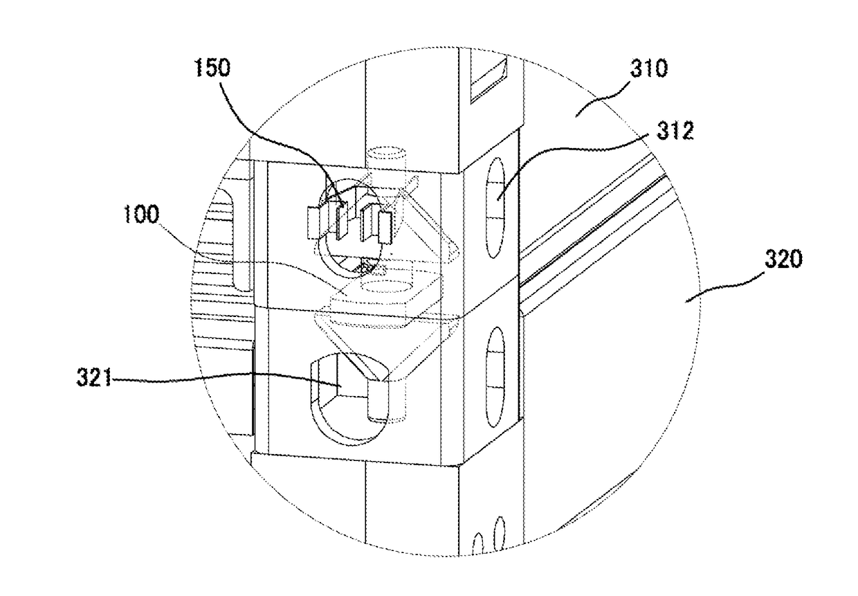
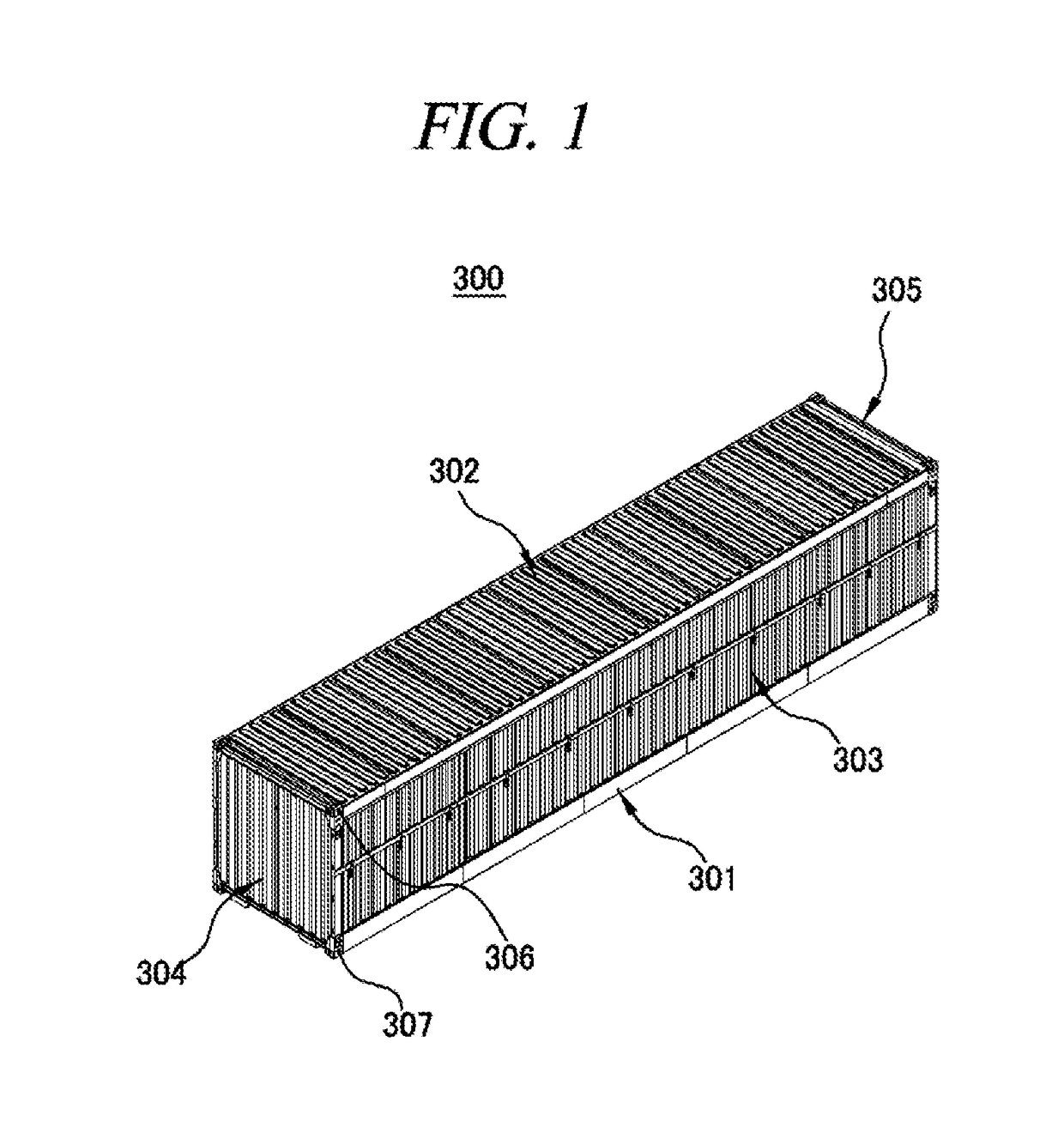
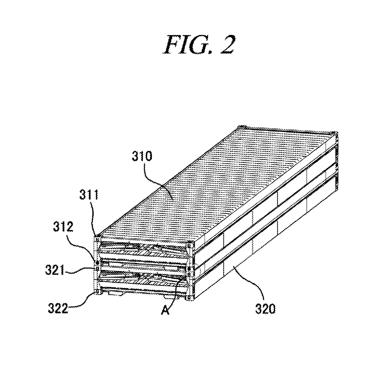
The present invention is a locking device for containers that is fully inserted and fixed to a hole formed in a corner fitting of a container. This design prevents a space between the container and a vertically adjacent container, maximizing space utilization. Additionally, the use of a fastening fixing unit provides stability and visual check of the fastening state of containers, reducing safety accidents.

Problems solved by technology

Therefore, if the conventional container locking device is used when multiple containers are stacked vertically to be stored or transported on a ship or truck, the main body of the locking device is positioned between the containers and thus unnecessarily requires a space.
Furthermore, when multiple containers are stacked using the conventional container locking device, it is difficult to visually check whether or not the container locking device is properly fastened, and, thus, there is a risk of safety accident.

Method used


Image

  • Locking device for containers
  • Locking device for containers
  • Locking device for containers

Examples


Embodiment Construction

[0032]Hereinafter, embodiments of the present disclosure will be described in detail with reference to the accompanying drawings so that the present disclosure may be readily implemented by those skilled in the art. However, it is to be noted that the present disclosure is not limited to the embodiments but can be embodied in various other ways. In drawings, parts irrelevant to the description are omitted for the simplicity of explanation, and like reference numerals denote like parts through the whole document.

[0033]Through the whole document, the term “connected to” or “coupled to” that is used to designate a connection or coupling of one element to another element includes both a case that an element is “directly connected or coupled to” another element and a case that an element is “electronically connected or coupled to” another element via still another element.

[0034]Through the whole document, the term “on” that is used to designate a position of one element with respect to a...


PUM


Abstract

The present disclosure suggests a locking device for containers. A locking device for containers according to an exemplary embodiment of the present disclosure includes: a housing including a base part, a protrusion protruded upwards from an upper surface of the base part, and a through hole formed by penetrating the base part and the protrusion in a vertical direction; a connection part rotatably inserted into the through hole of the housing; an upper cone positioned on the connection part and inserted into a lower corner fitting of a first container positioned on an upper end; and a lower cone positioned under the connection part and inserted into an upper corner fitting of a second container positioned on a lower end.

Description

TECHNICAL FIELD[0001]The present disclosure relates to a locking device for containers.BACKGROUND[0002]In general, a container includes four corner beams as supports and panels each having a predetermined area as six surfaces, i.e., front, rear, left, right, top, and bottom surfaces, between the supports and interlocked and assembled by welding or using a fastening means such as rivet to form a space therein for transport or storage of freight.[0003]In a container, a corner fitting is positioned at each corner. The corner fitting is used to fasten a container to a container transport device when the container is moved to a predetermined position and also used to fix containers positioned adjacent to each other.[0004]Further, when stored or transported on a ship or the like, multiple containers are stacked and loaded in multiple stages in a vertical direction. In this case, the containers stacked in a vertical direction are fixed using a container locking device at each corner fittin...

Claims


Application Information

Patent Timeline
IPC IPC(8): E05B83/02B65D88/12B65D90/22
CPCE05B83/02B65D88/124B65D88/129B65D90/22B63B25/00B65D90/0013E04B1/3483Y10T403/7005
Inventor KIM, HAG SEOUNGKWON, YONG JANGKIM, YOUNG JOOKANG, SUNG WOOKRHEE, YOUNG HO
Owner KOREA RAILROAD RES INST
Why Eureka
Try Eureka