
Printer with image inspection device

a technology of image inspection and printer, which is applied in the field of printers, can solve the problems of large dimensions and large printed images

Inactive Publication Date: 2018-06-21
OCE HLDG BV
View PDF4 Cites 6 Cited by
  • Summary
  • Abstract
  • Description
  • Claims
  • Application Information

AI Technical Summary

Benefits of technology

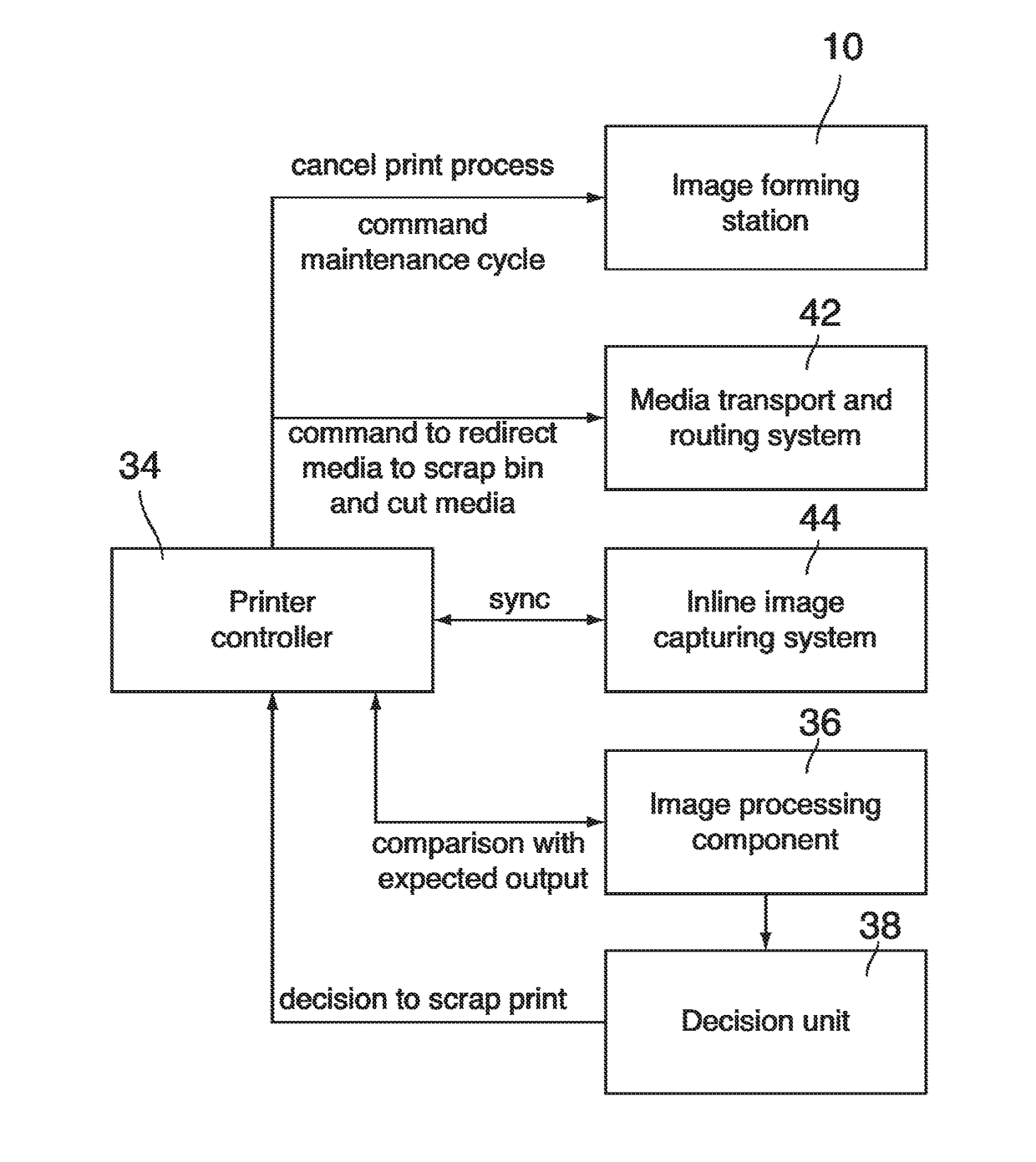
The invention is about a roll-to-sheet printer that can detect and reject defective prints automatically. It has a compact design and uses an output tray for temporary holding of the media. The image inspection device is positioned after the image forming station and the cutting device can be located upstream or downstream of the image forming unit. The technical effect of the invention is to improve print quality and reduce waste by identifying and eliminating defective prints.

Problems solved by technology

The problem with roll-to-sheet printers is that the printed images, since they are printed on an endless web, may have considerably large dimensions in the media transport direction.

Method used


Image

  • Printer with image inspection device
  • Printer with image inspection device
  • Printer with image inspection device

Examples


Embodiment Construction

[0032]The present invention will now be described with reference to the accompanying drawings, wherein the same reference numerals have been used to identify the same or similar elements throughout the several views.

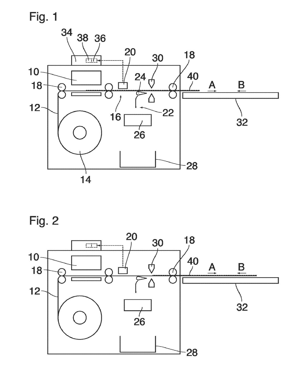
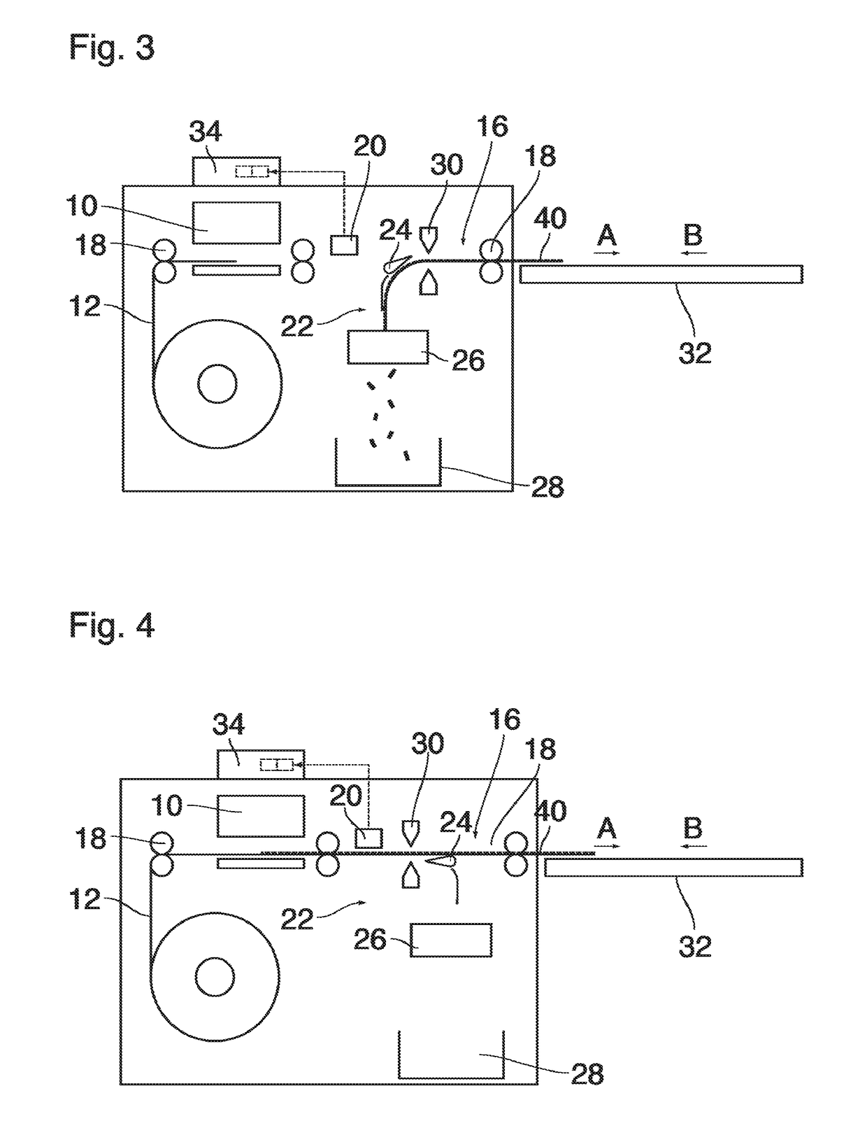
[0033]As is shown in FIG. 1, a printer according to the invention comprises an image forming station 10 arranged to form an image on a media that takes the form of an endless web 12 and is withdrawn from a roll 14. A first media transport path 16 is arranged to transport the web past the image forming station 10 and comprises pairs of feed rollers 18 which may be driven to move the web 12 either in a forward direction A or a rearward direction B.

[0034]An image inspection device 20 comprises a camera that is disposed at the media transport path 16 in a position downstream of the image forming station 10 so as to inspect an image that has just been printed onto the web in the image forming station 10.

[0035]A second media transport path 22 is arranged to branch off from the...


PUM


Abstract

A printer includes an image forming station; a first media transport path arranged to convey printed media from the image forming station to an output port; a second media transport path branching off from the first media transport path and arranged to convey printed media to a reject port; a switch for directing printed media into the second media transport path; an image inspection device for inspecting images printed onto the media; and a decision unit arranged to decide, on the basis of an inspection result obtained from the image inspection device, whether a printed image shall be rejected, and arranged to control the switch. The printer is a roll-to-sheet printer having a roll from which the media are supplied into the first media support path in the form of an endless web. The printer includes a cutting device for cutting the web; and the decision unit is arranged to cause a reversal of the transport direction of the media in the first media transport path, thereby to move an edge of the printed media to the position of the switch.

Description

BACKGROUND OF THE INVENTION1. Field of the Invention[0001]The invention relates to a printer comprising:[0002]an image forming station;[0003]a first media transport path arranged to convey printed media from the image forming station to an output port;[0004]a second media transport path branching off from the first media transport path and arranged to convey printed media to a reject port;[0005]a switch for directing printed media into the second media transport path;[0006]an image inspection device for inspecting images printed onto the media; and[0007]a decision unit arranged to decide, on the basis of an inspection result obtained from the image inspection device, whether a printed image shall be rejected, and arranged to control the switch.2. Description of Background Art[0008]US 2011 / 075 193 A1 discloses a cut-sheet printer which has the features listed above.SUMMARY OF THE INVENTION[0009]It is an object of the invention to provide a roll-to-sheet printer which is capable of au...

Claims


Application Information

Patent Timeline
IPC IPC(8): B41J13/00G03G15/00B41J11/66
CPCB41J13/0009G03G15/6582B41J11/663B02C18/00B41J2/2142B41J11/70B41J13/009B41J15/04B41J29/393B65H26/02B65H29/12B65H29/62B65H43/04G03G15/5062B65H2403/942B65H2404/14B65H2404/632G03G15/6517
Inventor NISTOR, MIRCEA
Owner OCE HLDG BV
Learn More