
Method for creating custom orthopedic supports from computerized data inputs

a computerized data and input method technology, applied in the field of orthopaedic inserts, can solve problems such as scoliosis and spine curvature, and achieve the effect of permanently correcting any spinal curvature and minimizing pain

Active Publication Date: 2018-06-07
SPECTOR DONALD
View PDF2 Cites 4 Cited by
  • Summary
  • Abstract
  • Description
  • Claims
  • Application Information

AI Technical Summary

Benefits of technology

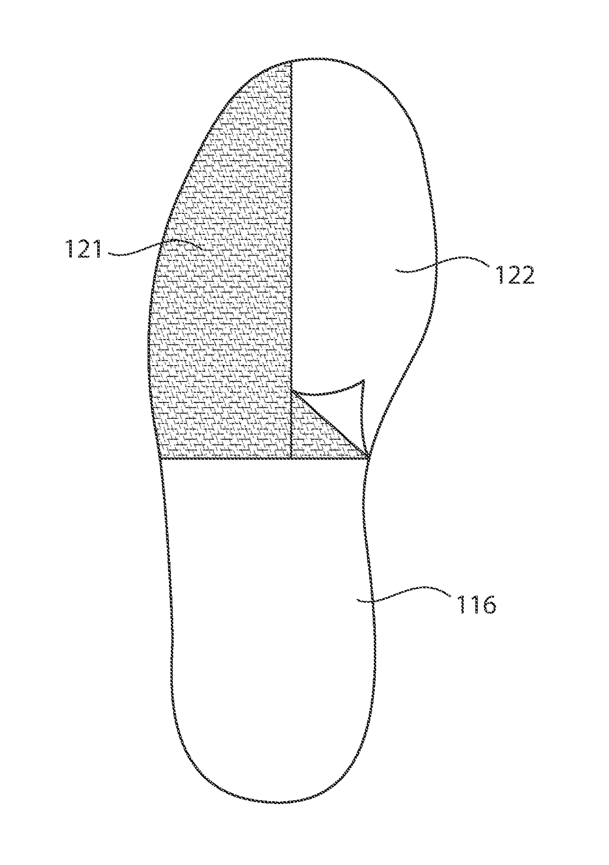
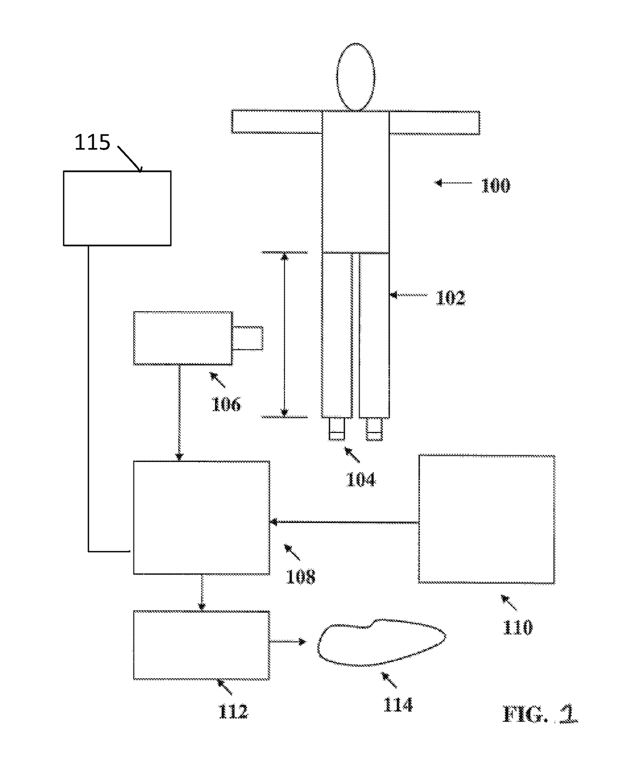
This patent describes a system that uses digital x-ray images to measure and analyze the spine and legs of patients. It detects abnormalities like scoliosis or limb length disorder and sends this information to a computer which designates an orthopedic implant for printing on a 3D printer. Foot size and shape are also considered by the computer when determining the best fit for the patient. The system automates the process of identifying issues and producing customized solutions to gradually improve spinal alignment and reduce pain during growth.

Problems solved by technology

The patent text discusses the field of orthopedic inserts for shoes and footwear. There are two main categories of products: universal insoles that provide general support and supports made by Podiatrists that correct weight and imprint of the foot. The technical problem addressed in the patent is the need for progressive foot orthotics that can prevent and treat scoliosis, a curvature in the spine, in adolescents with LLD.

Method used


Image

  • Method for creating custom orthopedic supports from computerized data inputs
  • Method for creating custom orthopedic supports from computerized data inputs
  • Method for creating custom orthopedic supports from computerized data inputs

Examples


Embodiment Construction

[0014]One object of this invention to create a collateral informational base that is immediately capable of altering the manufacture of inserts on a personal basis in an economic way. This can be particularly important since the cost of inserts by podiatrists typically cost hundreds of dollars, for an end product that probably has a cost of goods of only a few dollars. The computerized instructions for the manufacturing of the insert can be transmitted to a foreign country where these inserts can be made by hand or eventually transmitted to machines that can actually create three dimensional moldings that can then be sold to the consumers at a faction of the cost of present inserts sold by Podiatrists.

[0015]It is believed that almost 90% of the population has two different size legs. Typically, people with two different size legs learn to compensate for this difference by favoring one side. Experts in the field have shown that this is a primary cause of scoliosis, back problems, hip...


PUM


Abstract

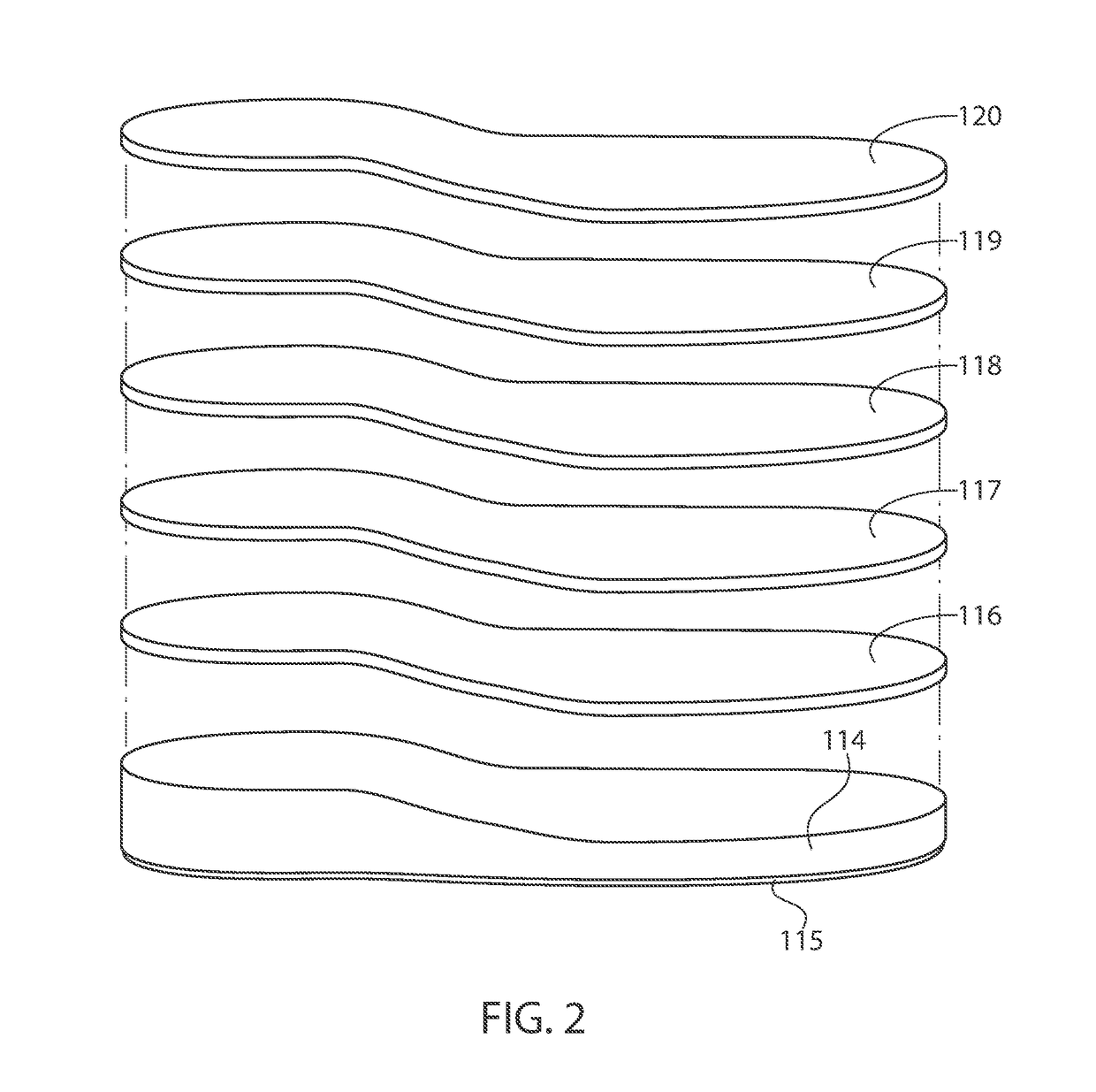
Systems and methods of measuring feet and designing and creating orthopedic inserts are described. A leg length discrepancy of a user is measured and this data, along with foot size are input into a computer. The computer then creates a computer model of a custom shoe insert based on this information. The computer model is then sent to a 3D printer to print the insert. The insert consists of a base insert with partial correction, and several additional layers that are added successively over time until a full correction is obtained. This eliminates any pain associated with a fully corrective insert, and allows the body to adjust gradually to the correction.

Description


Claims


Application Information

Patent Timeline
Owner SPECTOR DONALD
Learn More