
Projectile penetration resistance assemblies

a technology of projectiles and assemblies, applied in the direction of protective garments, synthetic resin layered products, furniture parts, etc., can solve the problems of increasing the number of new building construction, substantially increasing the number of new buildings, and the existing underlying structure associated with supporting the respective doors and windows is generally unsuitable for withstanding the additional load, so as to facilitate the formation of panels and facilitate workability

Active Publication Date: 2018-06-07
TRUARMOR A DIV OF CLEAR ARMOR LLC
View PDF21 Cites 3 Cited by
  • Summary
  • Abstract
  • Description
  • Claims
  • Application Information

AI Technical Summary

Benefits of technology

The present invention provides a kit for improving the impact and penetration resistance of glass sheets or panes. The kit includes brackets for mounting resistant glass panels and a gasket between each layer of glass and the mounting structure. An opaque panel made of reinforced fabric layers and adhesive can also be provided for projectile resistance. The panel is lightweight, flexible, and can be worked with common tools. The invention also includes a method for making the panel suitable for use in automotive, furniture, apparel, and building applications. The technical effects include increased resistance to impact and penetration, improved durability, and reduced weight and flexibility.

Problems solved by technology

Unfortunately, such approaches are not without their respective drawbacks.
Such an approach substantially increases new building construction and is generally cost prohibitive from a remodeling perspective.
Further, with respect to configuring existing structures to provide penetration resistance, the existing underlying structures associated with supporting the respective doors and windows are generally ill-suited to withstand the additional loading associated with replacement of such structures.
That is, storm proof windows and doors are generally substantially heavier than traditional window and door frame assemblies.
Such considerations are more problematic in multi-floored structures and / or structures having floor-to-ceiling window and / or door panels wherein the underlying structural framing is ill-suited to withstand the addition forces associated with penetration resistant window and door panels and the weight and forces customary thereto.
Personal vehicles are also occasionally equipped with such armaments but usually only at such great expense that only the extremely wealthy or otherwise potentially political and / or famous public figures can afford such protections.
Although steel plating is a common approach for the non-transparent structures of the underlying vehicle portions, such an approach substantially increases the weight of the underlying vehicle and the considerations attentive thereto as discussed above.
Such considerations render customary penetration resistance configurations unsuitable for many applications wherein persons disposed within a vehicle may be better served by being able to return fire or otherwise defend themselves with respect to acts of aggression directed toward the persons contained in the underlying vehicle.
Such assemblies are customarily configured to accommodate desired degrees of movement of the underlying wearer and commonly sacrifice penetration resistance in favor of the weight borne by the user as well as maintaining the desired degree of freedom of physical motion for the wearer.
Although some such forms of personal physical armaments are provided in flexible garments associated with containing respective discrete penetration resistant panels, such assemblies commonly provide unprotected areas between the discrete panels which facilitate the flexible movement of the respective supporting garment associated therewith.
As such, such assemblies present the opportunity for projectile penetrations for those areas that do not include or otherwise present the seam edges between discrete penetration resistant panels.
Such panels are commonly provided in a conveniently replaceable configuration but are generally flat and cannot otherwise be contoured to the underlying anatomy associated with the wearer.
Additionally, such personal physical armaments and / or apparel are generally heavy thereby limiting the duration with which a person can function while wearing such armaments and requires a degree of fitness uncommon to much of the populous including youth.

Method used


Image

  • Projectile penetration resistance assemblies
  • Projectile penetration resistance assemblies
  • Projectile penetration resistance assemblies

Examples


Embodiment Construction

[0035]The present invention and the various features and advantageous details thereof are explained more fully with reference to the non-limiting embodiments described in detail in the following description.

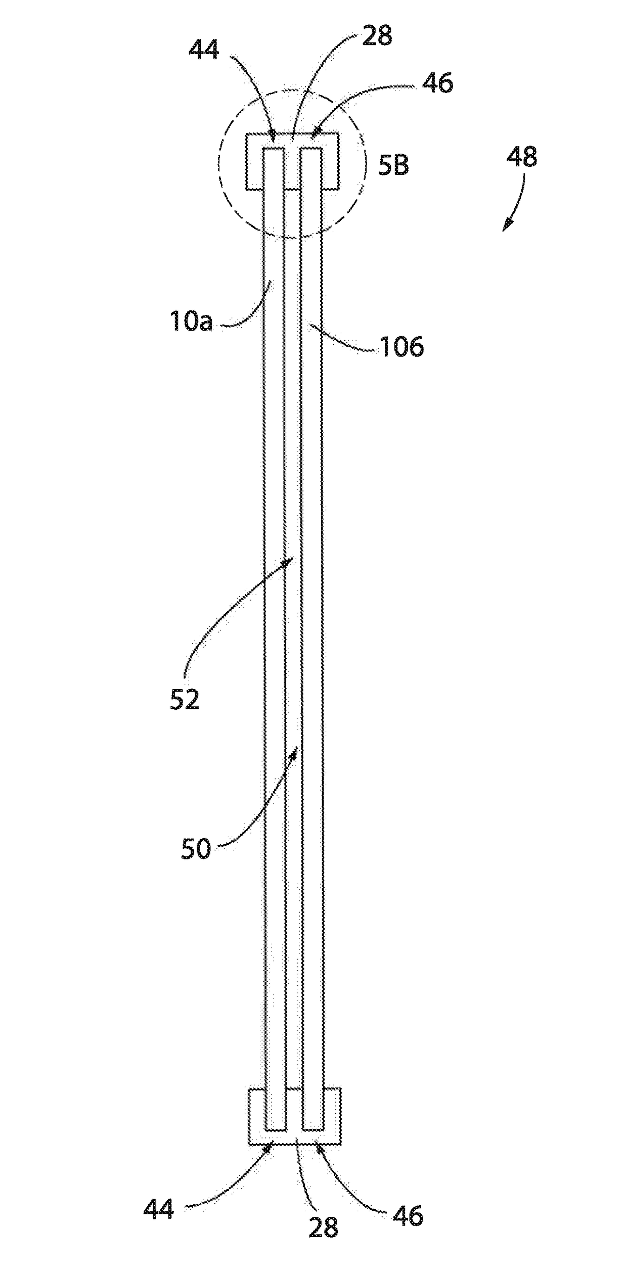
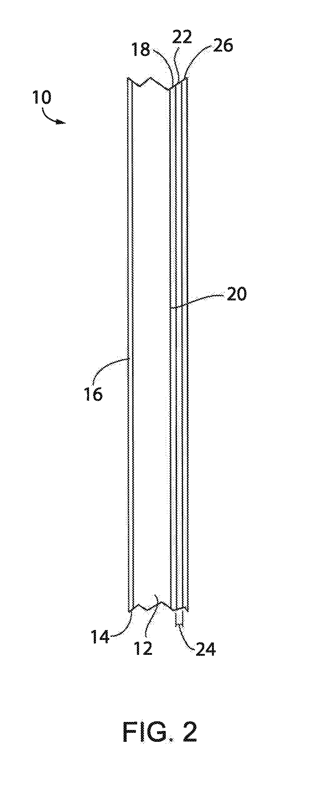
[0036]FIGS. 1 and 2 show a treated glass pane or window 10 that has undergone a glass treatment process as disclosed herein is shown such that window 10 is rendered penetration resistant in one direction without substantially affecting the penetration resistance in an opposite direction. That is, treated glass window 10 is configured to resist passage of projectiles through the window in directions crossing the plane defined by the window pane in one direction and only minimally interfere with passage of projectiles in an opposite direction. Said in another way, once treated in the manner disclosed below, commercially available glass, whether provided in truly planar shapes (customary to building structures) or having a curved or otherwise non-planar or other contoured shaped (cu...


PUM

PropertyMeasurementUnit
angleaaaaaaaaaa
temperaturesaaaaaaaaaa

Abstract

Unidirectional transparent projectile penetration resistant panels and bidirectional opaque projectile penetration resistant assemblies and systems and methods of forming and mounting the same relative to underlying support structures.

Description

CROSS REFERENCE TO RELATED PATENT APPLICATIONS[0001]This application claims priority to U.S. Provisional Patent Application Ser. No. 62 / 426,694 filed on Nov. 28, 2016 titled “Uni-Directional Projectile Resistant Assembly” and claims priority to U.S. Provisional Patent Application Ser. No. 62 / 455,118 filed on Feb. 6, 2017 titled “Projectile Penetration Resistance Assemblies”, the disclosures of each of which are hereby expressly incorporated herein.BACKGROUND OF THE INVENTION[0002]Penetration resistance is a property that is desired in various environments and in various applications. Examples of such applications include providing structures that can withstand storm debris impacts, personal and vehicle armaments, etc. Understandably, the degree and nature of the penetration resistance performance is largely related to the use and construction of the underlying structure or vehicle as well as the ability of the structure, vehicle, or person to withstand the weight and forces associat...

Claims


Application Information

Patent Timeline
Patent Type & Authority Applications(United States)
IPC IPC(8): F41H5/04F41H7/00
CPCF41H5/263F41H5/0407F41H7/00B32B17/10027F41H5/013F41H5/0478F41H7/04B32B17/10073B32B2367/00B29C65/4835B29C66/1122B29C66/45B29C66/71B29L2031/3055B29L2031/768B32B3/06B32B3/08B32B5/26B32B7/12B32B27/06B32B27/304B32B37/12B32B38/0004B32B2037/1253B32B2250/03B32B2250/05B32B2250/40B32B2255/26B32B2262/0261B32B2307/41B32B2307/412B32B2307/50B32B2307/546B32B2307/558B32B2307/584B32B2307/732B32B2419/00B32B2437/00B32B2479/00B32B2571/02B32B2605/00B32B2605/003B32B2605/08F41H5/023F41H5/0485E06B3/5481E06B3/66347B29K2077/00B29C65/48B32B5/12B32B27/34F41H5/04
Inventor TRUDEAU, DAVID ANTHONY
Owner TRUARMOR A DIV OF CLEAR ARMOR LLC
Learn More