Developer container, developing apparatus, process cartridge and image forming apparatus

Active Publication Date: 2018-05-03
CANON KK
View PDF1 Cites 1 Cited by
  • Summary
  • Abstract
  • Description
  • Claims
  • Application Information

AI Technical Summary

Benefits of technology

The patent text discusses the problem of toner scattering and insufficient toner supply in image forming apparatuses. It notes that increasing the capacity of the toner storing chamber leads to longer stirring members, which causes bending and inclination, making it easier for toner to fall off the sheet and create blank dots in the image. The invention proposes a solution to control the falling of developer on the sheet and ensure sufficient toner supply to the developing chamber.

Problems solved by technology

However, if the capacity of the toner storing chamber is increased to store more toner, the distance between the rotation center axis line of the stirring member and the inner wall surface of the toner storing chamber becomes long, and the rotation radius of the stirring member increases.
Hence the amount of toner laying on the stirring member decreases, and the amount of toner to be supplied to the developing chamber becomes insufficient, which may generate blank dots in the image formed on the recording material.
Furthermore, in recent years, the process speed of image forming apparatuses have increased, which means that toner consumption amount per unit time is higher, and more toner must be transported to the developing chamber.

Method used


Image

  • Developer container, developing apparatus, process cartridge and image forming apparatus
  • Developer container, developing apparatus, process cartridge and image forming apparatus
  • Developer container, developing apparatus, process cartridge and image forming apparatus

Examples


example 1

[0046]Electro-photographic Image Forming Apparatus 100

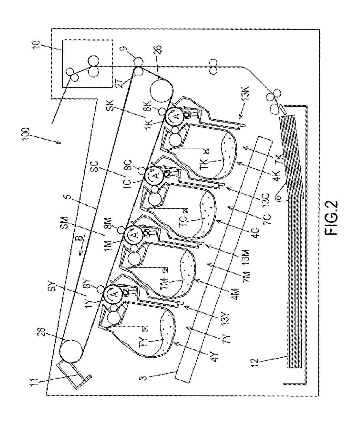
[0047]A general configuration of an electro-photographic image forming apparatus 100 (image forming apparatus 100) according to Example 1 will be described with reference to FIG. 2 and FIG. 3. FIG. 2 is a schematic diagram of the image forming apparatus 100 according to Example 1. FIG. 3 is a perspective view depicting a state of installing a process cartridge 7 in the image forming apparatus 100. The image forming apparatus 100 has a plurality of image forming portions SY to SK, which are first to fourth image forming portions for forming yellow (Y), magenta (M), cyan (C) and black (K) images respectively.

[0048]In Example 1, the first to fourth image forming portions have substantially the same configuration and perform the same operation, except that the color of the image to be formed is different. Therefore in the following description, the suffixes Y to K are omitted unless distinction is necessary. In Example 1, the image f...

example 2

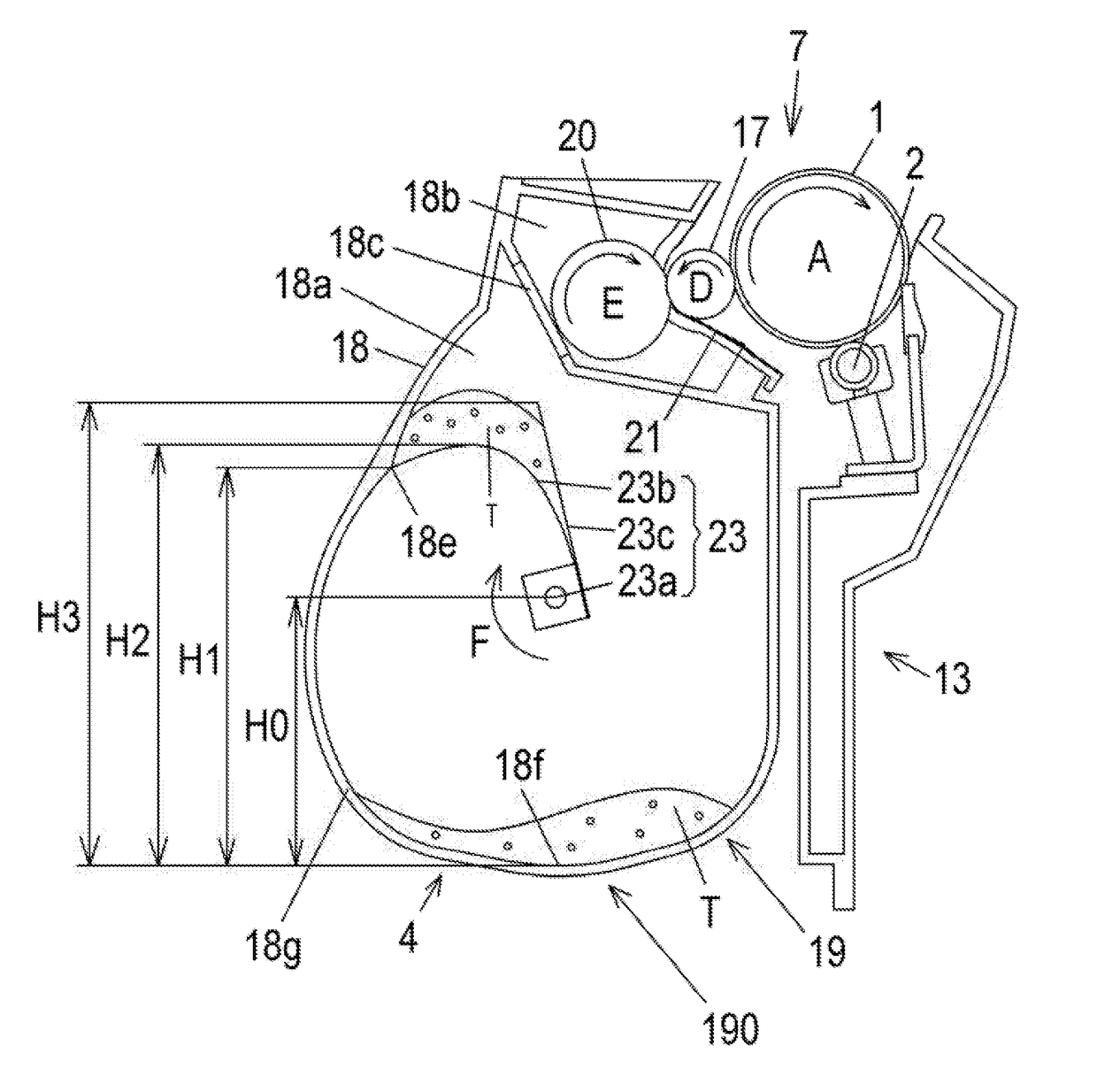
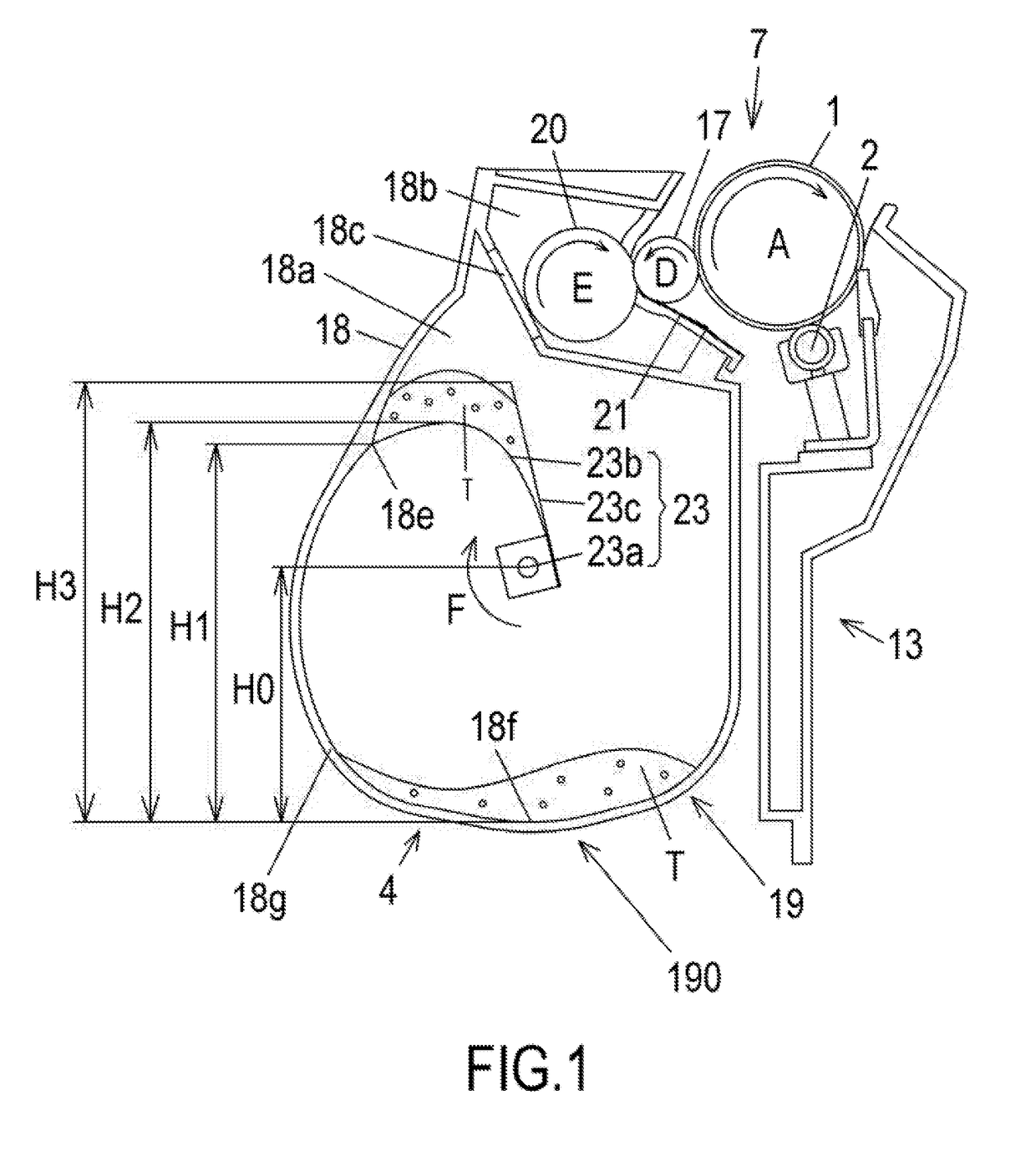
[0083]Example 2 will be described next. In Example 2, the basic configurations of the image forming apparatus and the process cartridge are the same as Example 1. Therefore in Example 2, a composing element having the same function as Example 1 is denoted with the same reference sign, and description thereof is omitted. FIG. 8 is a schematic cross-sectional view of the process cartridge according to Example 2.In Example 2, as illustrated in FIG. 8, a concave portion 18d is disposed in the toner storing chamber 18a, as a means of detecting the residual toner amount in the toner storing chamber 18a. The concave portion 18d is disposed on the upstream side of the release position 18e in the rotating direction of the stirring member 230. The concave portion 18d is also disposed in such a position that the toner on the stirring sheet 23b enters the concave portion 18d in the process of the stirring sheet 23b rotating with elevating the toner.

[0084]When the residual toner amount inside th...


PUM


Abstract

A developer container includes a second sheet member 23c that is installed on a rotation shaft 23a and rotates in the same phase as a first sheet member 23b, wherein when the rotation shaft 23a rotates in a state in which at least a part of the developer elevated by the first sheet member 23b is positioned above the rotation shaft 23a, the second sheet member 23b rotates on the downstream side of the first sheet member 23b, in the rotating direction of the rotation shaft 23a so as to control the falling of developer on the first sheet member 23b.

Description

BACKGROUND OF THE INVENTIONField of the Invention[0001]The present invention relates to a developer container to contain developer which is used for forming an image on a recording medium, and relates to a developing apparatus that develops an electrostatic latent image formed on a photosensitive drum. Further, the present invention relates to a process cartridge that forms a developer image on a photosensitive drum, and is attachable to and detachable from the main body of an image forming apparatus, and relates to an image forming apparatus that forms an image on a recording medium using developer.Description of the Related Art[0002]In the case of an image forming apparatus, such as a printer, which uses an electro-photographic image forming system (electro-photographic process), a photosensitive drum is uniformly charged by a charging roller first when an image is formed on a recording material. Then the charged photosensitive drum is selectively exposed by an exposing apparatus,...

Claims


Application Information

Patent Timeline
IPC IPC(8): G03G15/08
CPCG03G15/0889G03G15/0836G03G15/0875G03G2215/085G03G15/0808G03G15/0877G03G15/087
Inventor FUJIWARA, AKIHIROABE, TSUKASA
Owner CANON KK
Why Eureka
Try Eureka