Optical coherence tomography method, system and computer program product therefor

Active Publication Date: 2018-04-05
NEDERLANDSE ORG VOOR TOEGEPAST-NATUURWETENSCHAPPELIJK ONDERZOEK (TNO)
View PDF2 Cites 3 Cited by
  • Summary
  • Abstract
  • Description
  • Claims
  • Application Information

AI Technical Summary

Benefits of technology

The invention aims to offer an OCT method and system that can accurately correct the imaging beam.

Problems solved by technology

Although OCT has the potential to enable ophthalmologic imaging at high resolution, at present the lateral resolution is strongly limited by eye motions of the eye under examination.
However, the present tracking devices are still not accurate enough to compensate for eye motion sufficiently, to obtain the required accuracy for correcting the optical retinal imaging system.

Method used


Image

  • Optical coherence tomography method, system and computer program product therefor
  • Optical coherence tomography method, system and computer program product therefor
  • Optical coherence tomography method, system and computer program product therefor

Examples


Embodiment Construction

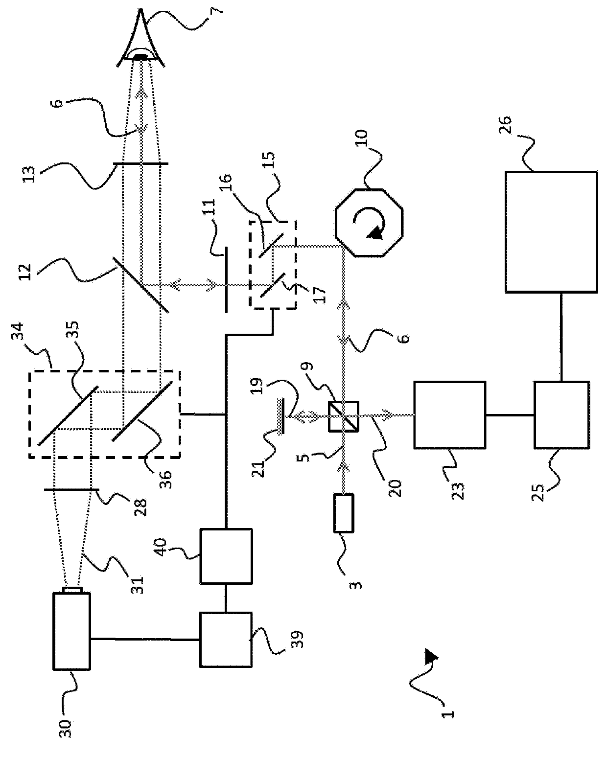
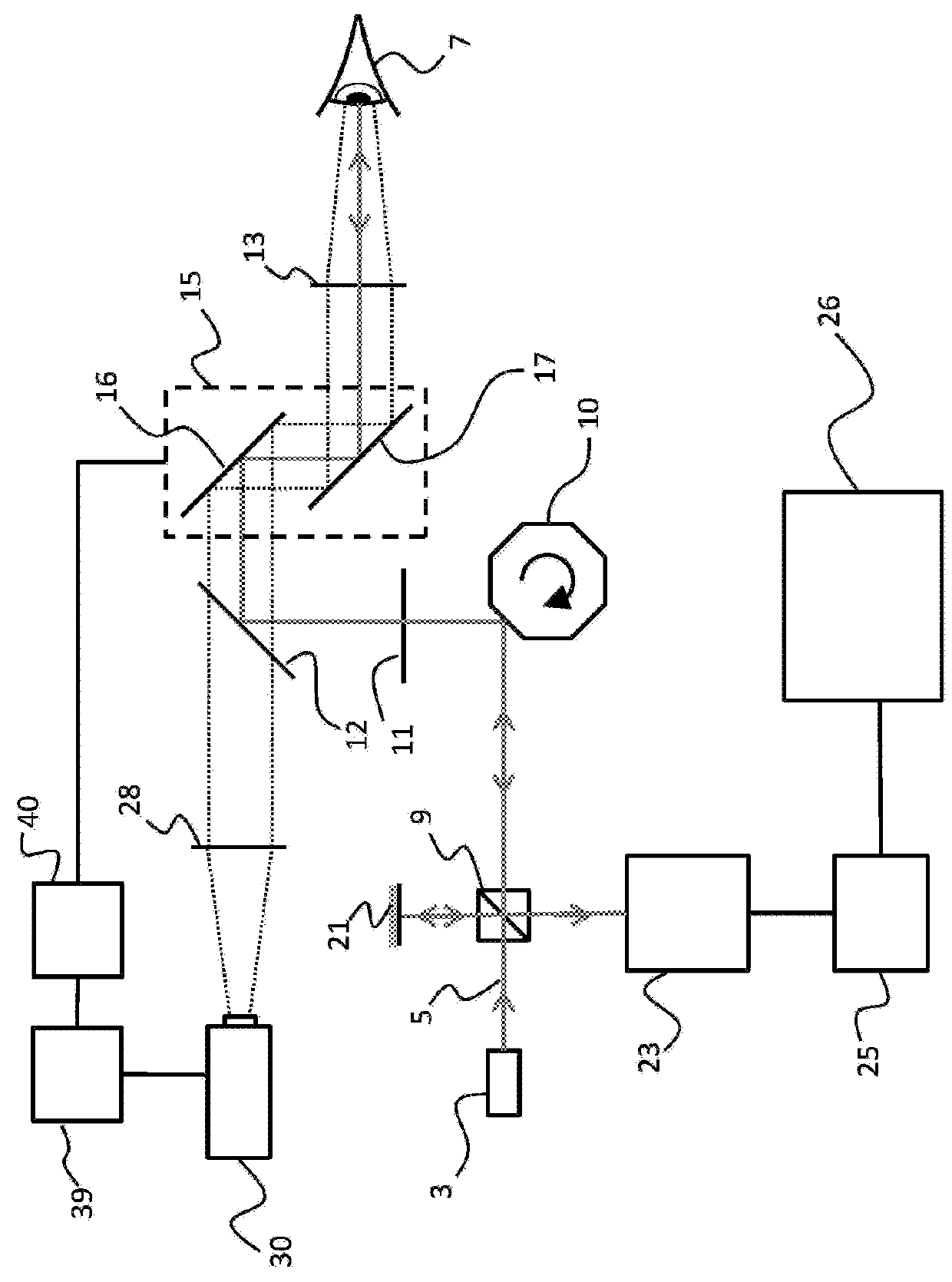
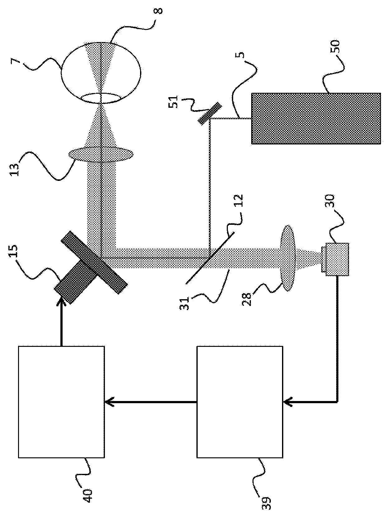
[0038]In FIG. 1, an optical coherent tomography [OCT] system is generally indicated by reference numeral 1. The system includes a radiation source 3 providing a beam 5 of imaging radiation. The beam 5 is directed towards an eye 7 of a human or animal, which eye 7 is to be examined. In particular, the optical coherent tomography system 1 allows for example to examine the fundus of the eye 7.

[0039]The beam 5 of imaging radiation is directed towards the eye 7 by means of a number of optical elements (10, 11, 12, 13 and 15). The optical elements for directing the beam 5 of imaging radiation may include lenses 11 and 13 for correctly focusing of the radiation. The optical elements further include a mirror element 12 which comprises a specular reflective surface on one side, but which is transmissive on the other side such as to allow the camera 30 to have a field of view with the eye 7 (as will be explained later). The optical elements further includes scanning optics 10 comprising a rot...


PUM


Abstract

The present invention relates to an optical coherence tomography method, comprising: providing a beam of imaging radiation from a radiation source of an optical coherence tomography apparatus; directing, using directing optics, the beam of imaging radiation towards a fundus of a human or animal eye; and receiving a reflected portion of the imaging radiation by the optical coherence tomography apparatus; wherein the method further comprises: providing, by a tracking camera, a tracking image of an image area covering at least a part of said fundus; analyzing the tracking image for detecting a displacement of the fundus; and adapting, at least dependent on the detected displacement, a direction of the beam of imaging radiation by actuating an optical correction unit of said direction optics; and in addition to said adapting of the direction of the beam of imaging radiation, adapting a location of the image area on said fundus imaged by the tracking camera at least dependent on the detected displacement.

Description

FIELD OF THE INVENTION[0001]The present invention is directed at an optical coherence tomography method, comprising providing a beam of imaging radiation from a radiation source of an optical coherence tomography apparatus; directing, using directing optics, the beam of imaging radiation towards a fundus of a human or animal eye; and receiving a reflected portion of the imaging radiation by the optical coherence tomography apparatus.[0002]The invention is further directed at an optical coherence tomography system, comprising an optical coherence tomography apparatus including a radiation source for providing a beam of imaging radiation, an optical receiver for receiving a reflected portion of the imaging radiation, and an analysis unit for analyzing the received reflected portion of the imaging radiation. The invention is further directed at a computer readable medium comprising computer program product.BACKGROUND[0003]Optical retinal imaging is class of a medical imaging techniques...

Claims


Application Information

Patent Timeline
IPC IPC(8): A61B3/10A61B3/12A61B3/14G01B9/02G06T5/50G06T1/00
CPCA61B3/102A61B3/1225A61B3/14G01B9/02091G06T5/50G06T1/0007A61B3/15
Inventor KUIPER, STEFANDOELMAN, NICOLAAS JANLIEBIG, THOMASKLOP, WILLEM ARJAN
Owner NEDERLANDSE ORG VOOR TOEGEPAST-NATUURWETENSCHAPPELIJK ONDERZOEK (TNO)
Why Eureka
Try Eureka