
Clutch system

a technology of clutch system and input ramp, which is applied in the direction of hybrid vehicles, mechanical equipment, transportation and packaging, etc., can solve the problems of relative rotation of input ramp and input ramp, speed difference between input ramp and output ramp, etc., and achieves easy and efficient adaptation of torque transmission and easy integration

Active Publication Date: 2018-03-29
SCHAEFFLER TECH AG & CO KG
View PDF4 Cites 1 Cited by
  • Summary
  • Abstract
  • Description
  • Claims
  • Application Information

AI Technical Summary

Benefits of technology

The patent relates to a powertrain for a hybrid vehicle that can easily adapt to different driving strategies. It includes a torque-introducing element, a torque-discharging element, a clutch system, and an electric machine. The clutch system allows for efficient transfer of torque between the two elements, and the electric machine can be used to provide additional braking capacity. The technical effect of this patent is to provide a powertrain that can be adapted to different driving strategies, especially when the vehicle is intended to be driven in a purely electric way.

Problems solved by technology

When the pilot clutch is closed, the input ramp of the ramp system is coupled to the torque-introducing element and the output ramp is coupled to the torque-discharging element, resulting in a speed difference between the input ramp and the output ramp, which leads to rotation of the input ramp relative to the output ramp.

Method used


Image

  • Clutch system
  • Clutch system
  • Clutch system

Examples


Embodiment Construction

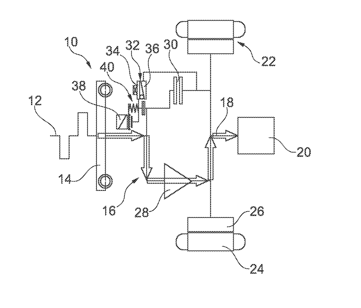
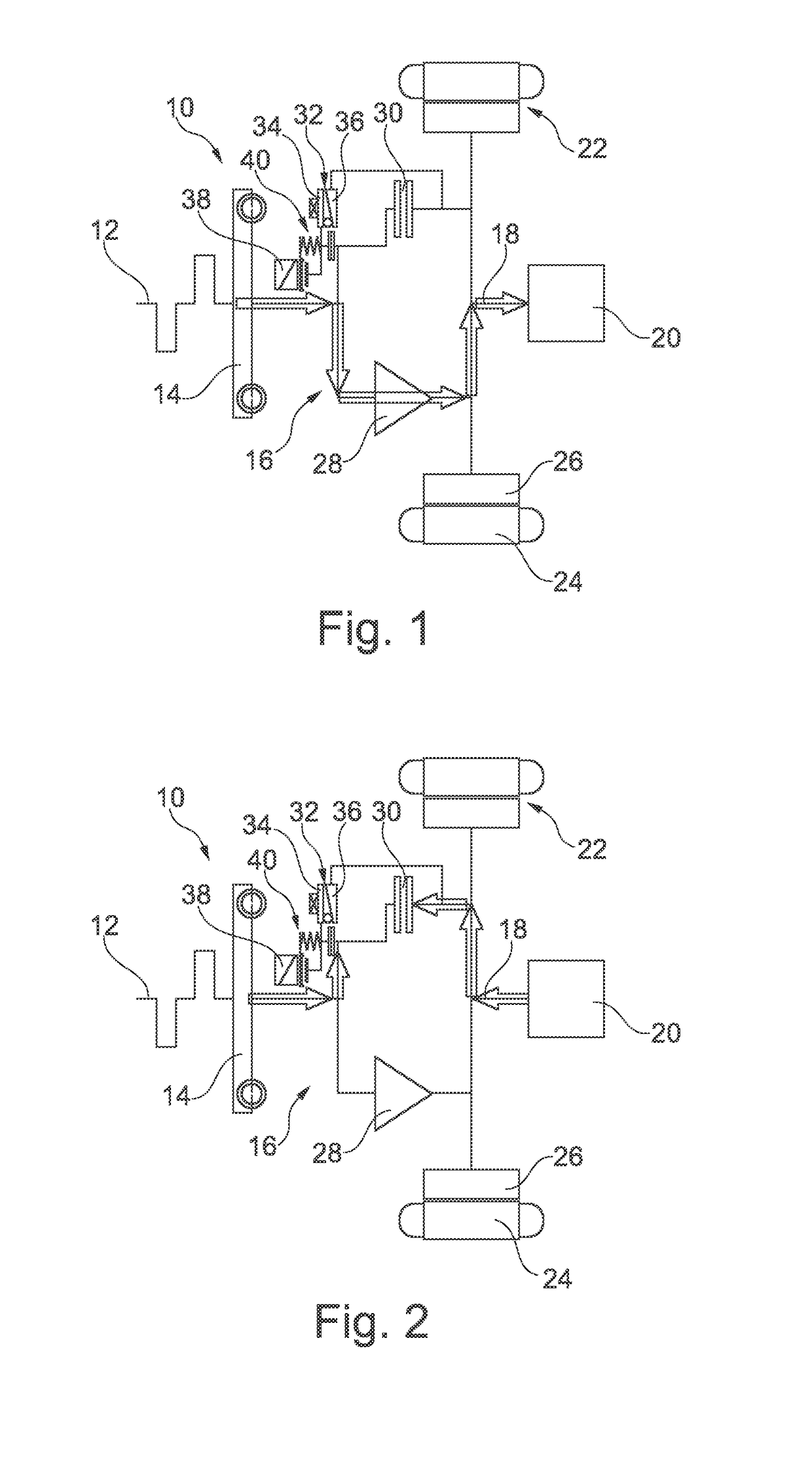
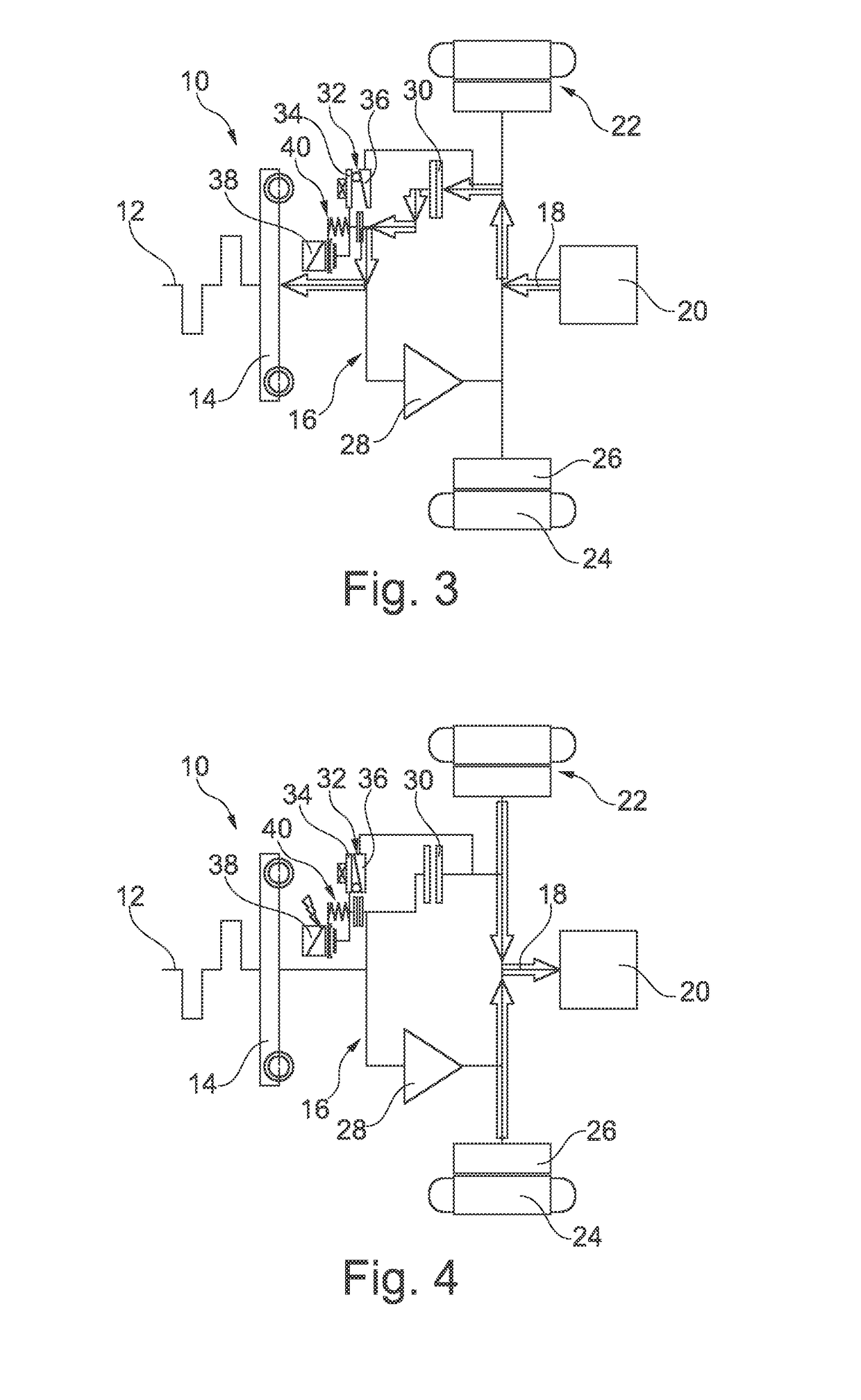
[0029]The powertrain 10 illustrated in FIG. 1 has a torque-introducing element 12 in the form of a drive shaft of a motor vehicle engine designed as a crankshaft, which can be coupled to a torque-discharging element 18 in the form of a transmission input shaft of a motor vehicle transmission 20 via a torsional vibration damper 14 in the form of a dual-mass flywheel and a clutch system 16. An electric machine 22 can also engage on the torque-discharging element 18 in order to exchange torque. For this purpose, the electric machine 22 has a stator 24, through which current can flow and which can interact with a rotor 26 coupled to the torque-discharging element 18. If appropriate, a separating clutch can be provided between the torque-introducing element 18 and the clutch system 16 and / or between the clutch system 16 and the torque-discharging element 18 in order to be able to select gears in the motor vehicle transmission 20 while the motor vehicle engine is running.

[0030]The clutch ...


PUM


Abstract

A clutch system includes a friction clutch and a ramp system. The friction clutch is a multiplate clutch, for example, for transmitting a torque between a torque-introducing element (i.e., an engine drive shaft) and a torque-discharging element (i.e., a transmission input shaft). The ramp system includes an input ramp, an output ramp, a pilot clutch, an actuation element, and a freewheel. The output ramp is rotatable relative to the input ramp to change an axial extent of the ramp system. The pilot clutch is for initiating rotation of the input ramp relative to the output ramp when there is a differential speed between the torque-introducing element and the torque-discharging element. The actuation element is for actuating the pilot clutch. The freewheel is arranged in a torque path in parallel with the friction clutch, and arranged to transmit a torque flow from the torque-introducing element to the torque-discharging element and interrupt a torque flow from the torque-discharging element to the torque-introducing element.

Description

CROSS-REFERENCE TO RELATED APPLICATIONS[0001]This application is the United States National Phase of PCT Appln. No. PCT / DE2016 / 200141 filed Mar. 15, 2016, which claims priority to German Application Nos. DE102015207041.7 filed Apr. 17, 2015, DE102015207039.5 filed Apr. 17, 2015, and DE102015209791.9 filed May 28, 2015, the entire disclosures of which are incorporated by reference herein.TECHNICAL FIELD[0002]The present disclosure relates to a clutch system, with the aid of which a drive shaft of a motor vehicle engine can be coupled to at least one transmission input shaft of a motor vehicle transmission, for example, in a hybrid motor vehicle.BACKGROUND[0003]WO 2011 / 050773 A1 discloses a clutch system in the form of a “booster clutch”, in which a friction clutch designed as a separating clutch can be actuated with the aid of a ramp system. To close the friction clutch, the ramp system can change its axial extent by means of an output ramp, which can be rotated relative to an input ...

Claims


Application Information

Patent Timeline
Patent Type & Authority Applications(United States)
IPC IPC(8): F16D27/112F16D13/52F16D47/04F16D41/04
CPCF16D27/112F16D13/52F16D47/04F16D41/04F16D2023/123B60K6/387F16D47/00B60K6/383B60K6/48B60K2006/4825F16D13/54F16D27/115Y02T10/62F16D13/74
Inventor TRINKENSCHUH, ANDREASREITZ, DIERK
Owner SCHAEFFLER TECH AG & CO KG
Learn More