
Charge and discharge device for electric vehicle

a technology for electric vehicles and charging devices, applied in electric vehicle charging technology, charging stations, transportation and packaging, etc., can solve the problem of requiring a certain amount of installation space, and achieve the effect of reducing the amount of forward projection, and facilitating the use of small spa

Active Publication Date: 2018-03-29
KAWAMURA ELECTRIC INC +1
View PDF19 Cites 6 Cited by
  • Summary
  • Abstract
  • Description
  • Claims
  • Application Information

AI Technical Summary

Benefits of technology

The disclosed invention includes a holder for a charge connector that is installed on a wall surface. The holder is mounted on a tapered surface, which allows the charge connector to face obliquely away from the wall surface. This prevents interference with the wall surface and reduces the likelihood of injury from contact with the charge connector. Additionally, the invention includes a housing with a reduced amount of forward projection, which makes it less likely for a person to touch the charge connector while getting on or off an automobile. The holder is stable and securely mounted on the tapered surface, even with an inclined surface. These features improve the overall safety and efficiency of the invention.

Problems solved by technology

A charge and discharge device for an electric vehicle with a cable having a charge connector for coupling to an electric vehicle at its distal end includes a cable holding portion at which the cable is wound and held, a holder which holds the charge connector, and similar portions, thus requiring a certain amount of installation space.
However, since the charge connector projects ahead viewing from the wall surface, a worker who gets on and off a vehicle has sometimes contacted the charge connector to break the charge connector and the holder.

Method used


Image

  • Charge and discharge device for electric vehicle
  • Charge and discharge device for electric vehicle
  • Charge and discharge device for electric vehicle

Examples


Embodiment Construction

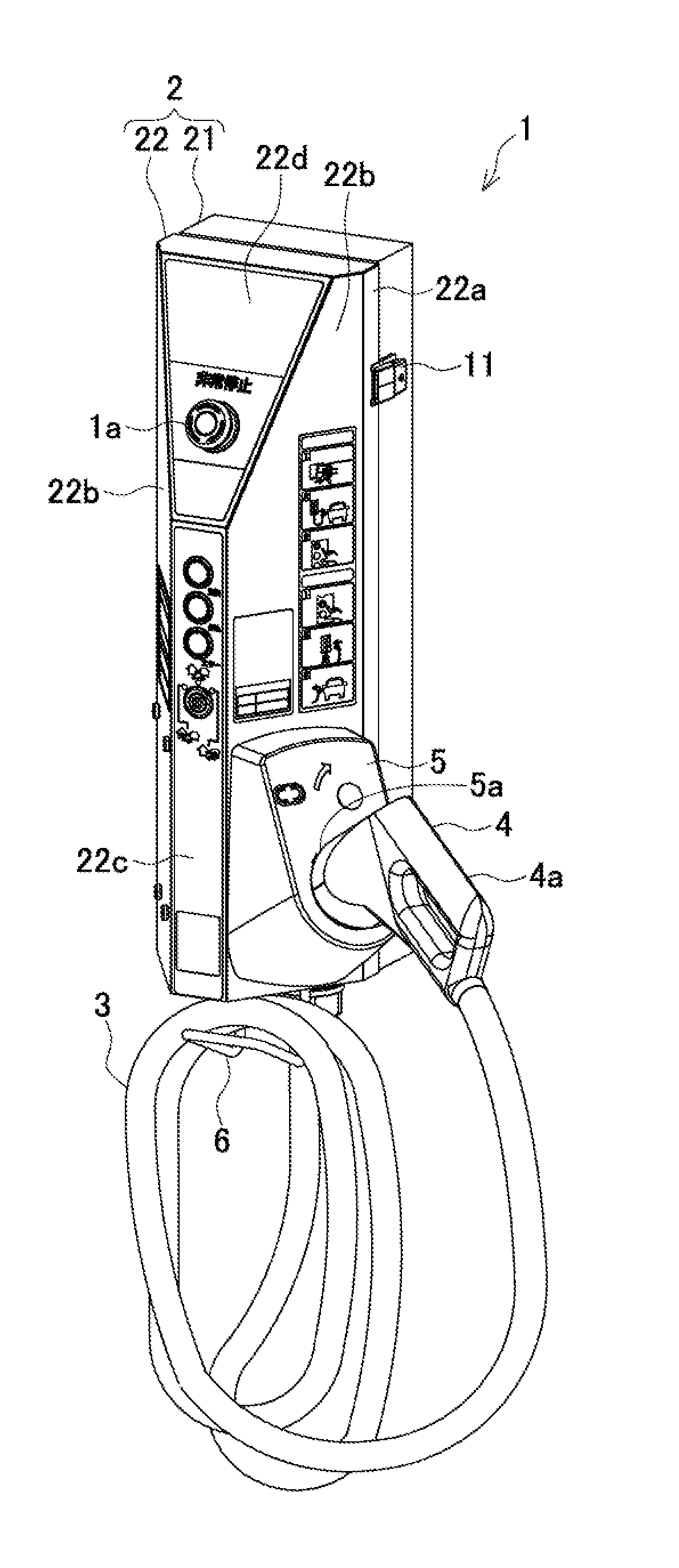
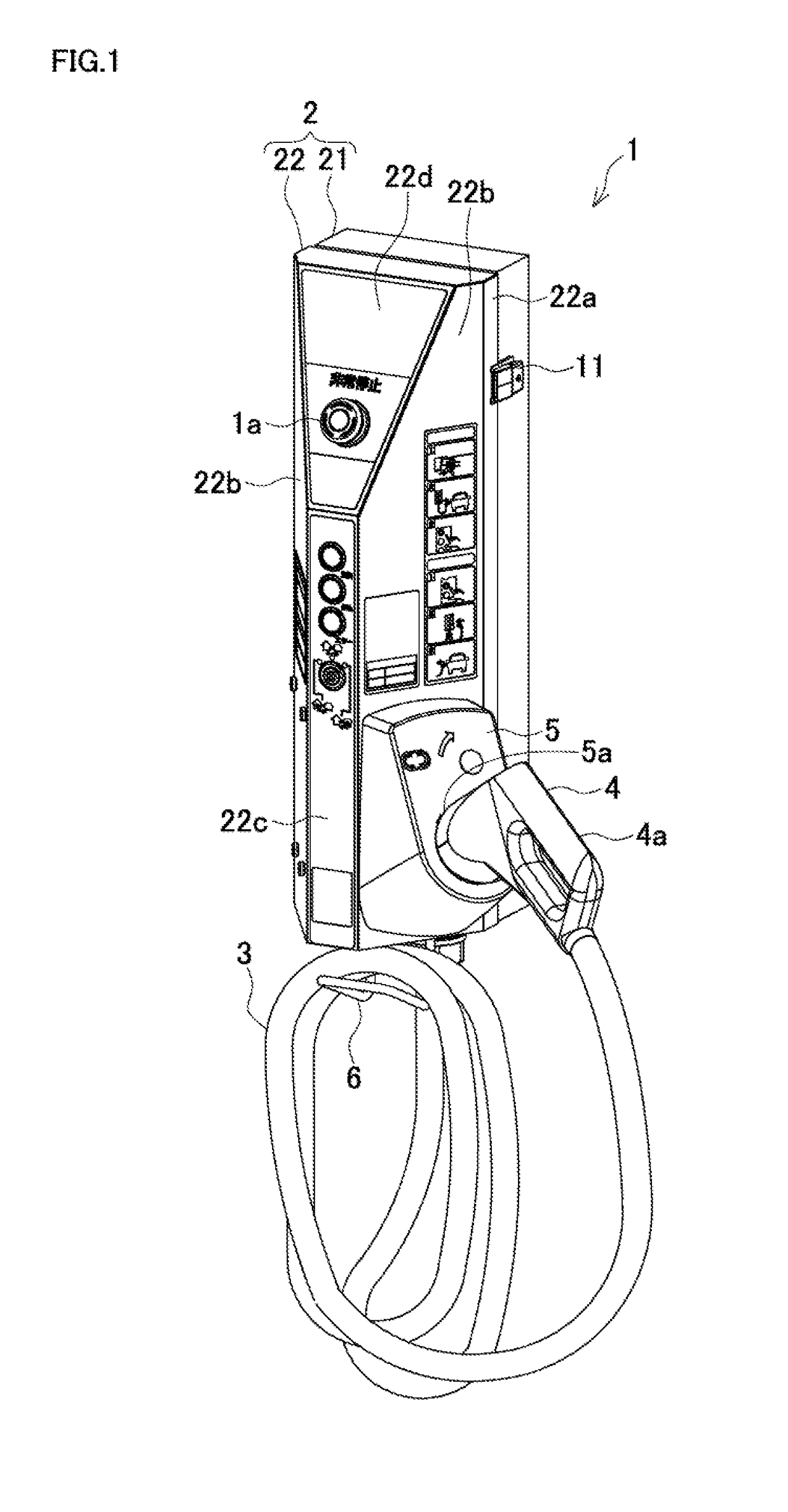
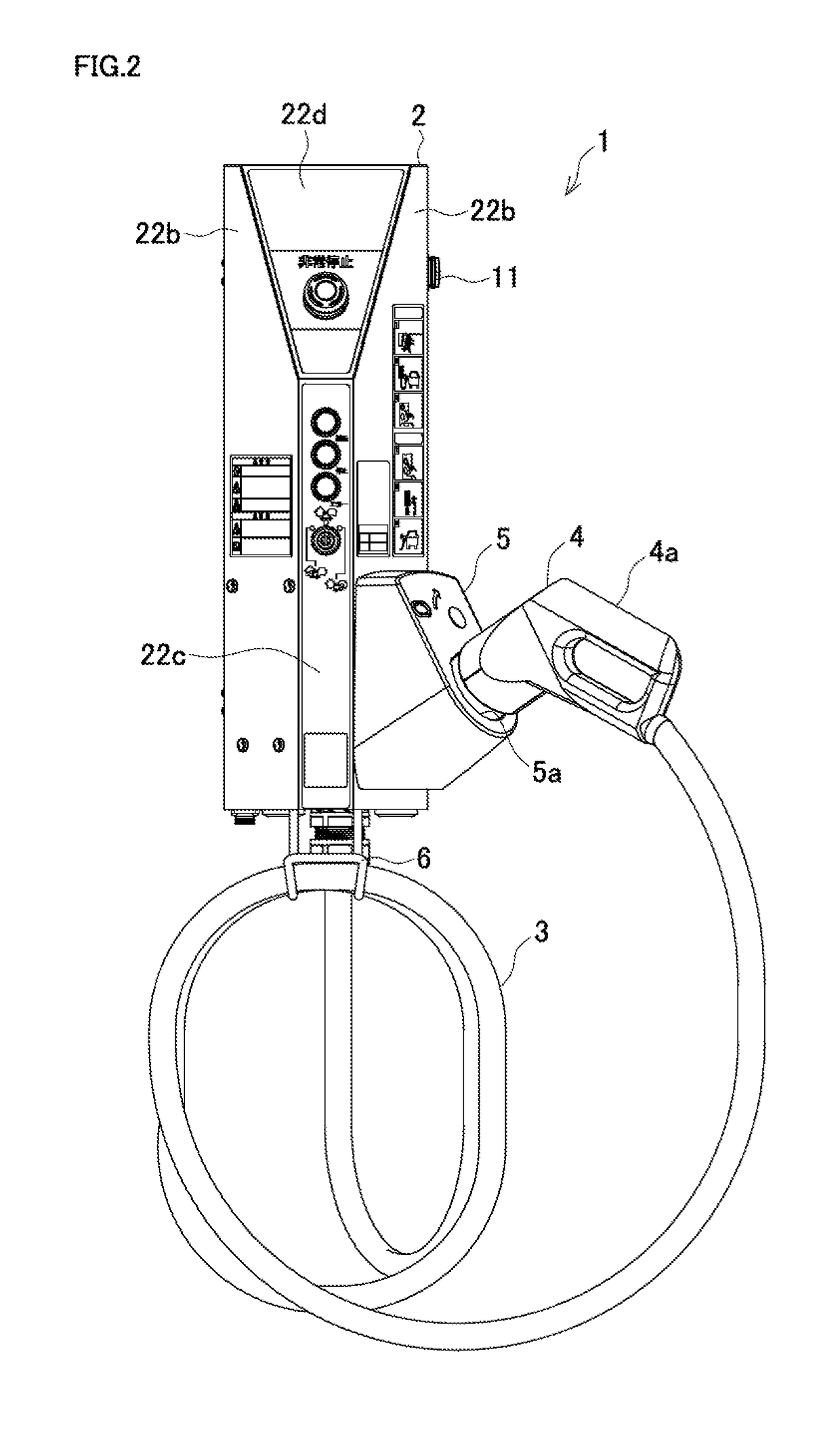
[0018]The following describes an embodiment where the disclosure is embodied in detail with reference to the drawings. FIG. 1 to FIG. 3 illustrate an exemplary charge and discharge device for an electric vehicle according to the disclosure. FIG. 1 is a perspective view, FIG. 2 is a front view, and FIG. 3 is a plan view.

[0019]A charge and discharge device 1 for an electric vehicle has a metal housing 2 mounted on a wall surface to house a terminal block, and a circuit board. The charge and discharge device 1 for the electric vehicle includes a cable 3, a charge connector 4, a holder 5, a cable suspending portion 6, and similar components. The cable 3 is extracted from the housing 2 and incorporates an electric wire. The charge connector 4 is disposed at a distal end of the cable 3 to be coupled to an electric vehicle. The holder 5 holds the charge connector 4. The cable 3 is wound around and held by the cable suspending portion 6.

[0020]The charge and discharge device 1 for the electr...


PUM


Abstract

A charge and discharge device for an electric vehicle includes a cable, a holder, and a cable suspending portion. The cable has a distal end at which a charge connector is provided. The charge connector is coupled to an electric vehicle to charge and discharge. The holder holds the charge connector. The cable suspending portion suspends and holds the cable. The holder and the cable suspending portion are disposed at a housing installed on a wall surface. The cable is extracted from the housing. The housing has a side portion at which a tapered surface as a surface facing obliquely ahead is disposed. The holder is mounted on the tapered surface.

Description

BACKGROUND[0001]This application claims the benefit of Japanese Patent Application Number 2016-187325 filed on Sep. 26, 2016, the entirety of which is incorporated by reference.TECHNICAL FIELD[0002]The disclosure relates to a charge and discharge device for an electric vehicle to charge and discharge an electric vehicle and a plug-in hybrid vehicle, and especially, relates to a charge and discharge device for an electric vehicle which includes a cable and is to be installed on a wall surface.RELATED ART[0003]A charge and discharge device for an electric vehicle, which is installed at a residence and the like, is formed in a small size so as not to interfere at a limited space such as a parking area. A charge and discharge device for an electric vehicle with a cable having a charge connector for coupling to an electric vehicle at its distal end includes a cable holding portion at which the cable is wound and held, a holder which holds the charge connector, and similar portions, thus ...

Claims


Application Information

Patent Timeline
Patent Type & Authority Applications(United States)
IPC IPC(8): B60L11/18
CPCB60L11/1824B60L2230/12B60Y2200/91B60L11/1816B60L53/14B60L53/31Y02T90/14B60L53/30B60L53/18Y02T10/70Y02T10/7072Y02T90/12
Inventor MURASE, HARUHIKOTAKAHASHI, NORIOOGAWA, MAKOTOOKADO, MICHIHITO
Owner KAWAMURA ELECTRIC INC
Learn More