
Ultrasonic stimulation device using guide framework

a technology of ultrasonic stimulation and guide framework, which is applied in the field of ultrasonic stimulation devices, can solve the problems of significant increase of manufacturing costs, difficulty in targeting stimulation to a specific site, and control error in the course of controlling each motor

Active Publication Date: 2018-03-08
KOREA INST OF SCI & TECH
View PDF7 Cites 4 Cited by
  • Summary
  • Abstract
  • Description
  • Claims
  • Application Information

AI Technical Summary

Benefits of technology

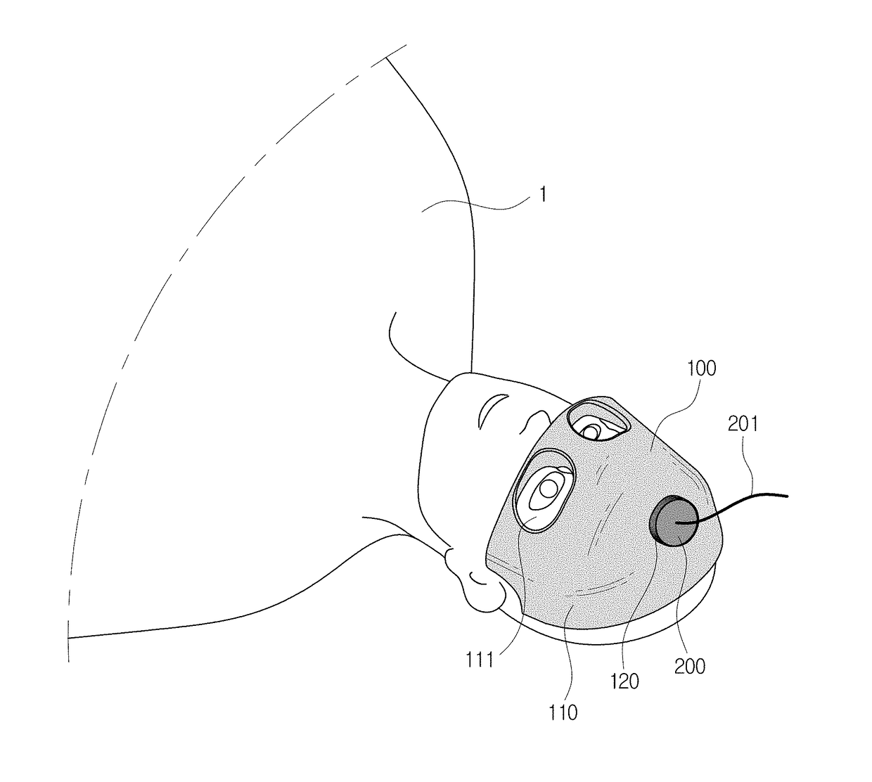
The present patent is about providing a guide framework for positioning an ultrasonic transducer for brain surgery without an electric control device. The guide framework includes a mask body that is placed on the subject's face and has a positioning hole through which the ultrasonic transducer is inserted. The mask body is formed to conform to the facial contour of the subject. The guide framework can be manufactured using a 3-dimensional printing process. The technical effect of this patent is to provide a reliable and efficient way to position the ultrasonic transducer for brain surgery without the need for an electric control device.

Problems solved by technology

A typical neural stimulation method is electrical stimulation, but the limitations of the electrical stimulation method are that a process for inserting electrodes is necessary and involves invasion into a patient's body, and targeted stimulation to a specific site is difficult due to a chain of electrical reactions in the living body.
However, a control error may occur in the course of controlling each motor 51, 52, 53 to control the central position O′ of the ultrasonic transducer 200.
Moreover, apart from the known MRI-compatible ultrasonic transducer 200, various types of electric devices including motors should be designed as MRI-compatible devices, which significantly increases the manufacturing costs.

Method used


Image

  • Ultrasonic stimulation device using guide framework
  • Ultrasonic stimulation device using guide framework
  • Ultrasonic stimulation device using guide framework

Examples


Embodiment Construction

[0053]Hereinafter, the preferred embodiments of the present disclosure are described with reference to the accompanying drawings. The present disclosure is described by referring to the embodiments shown in the drawings, but this is provided for illustration only, and the technical spirit of the present disclosure and its key elements and operation are not limited thereby.

[0054]FIG. 6 shows an ultrasonic stimulation device according to an embodiment of the present disclosure.

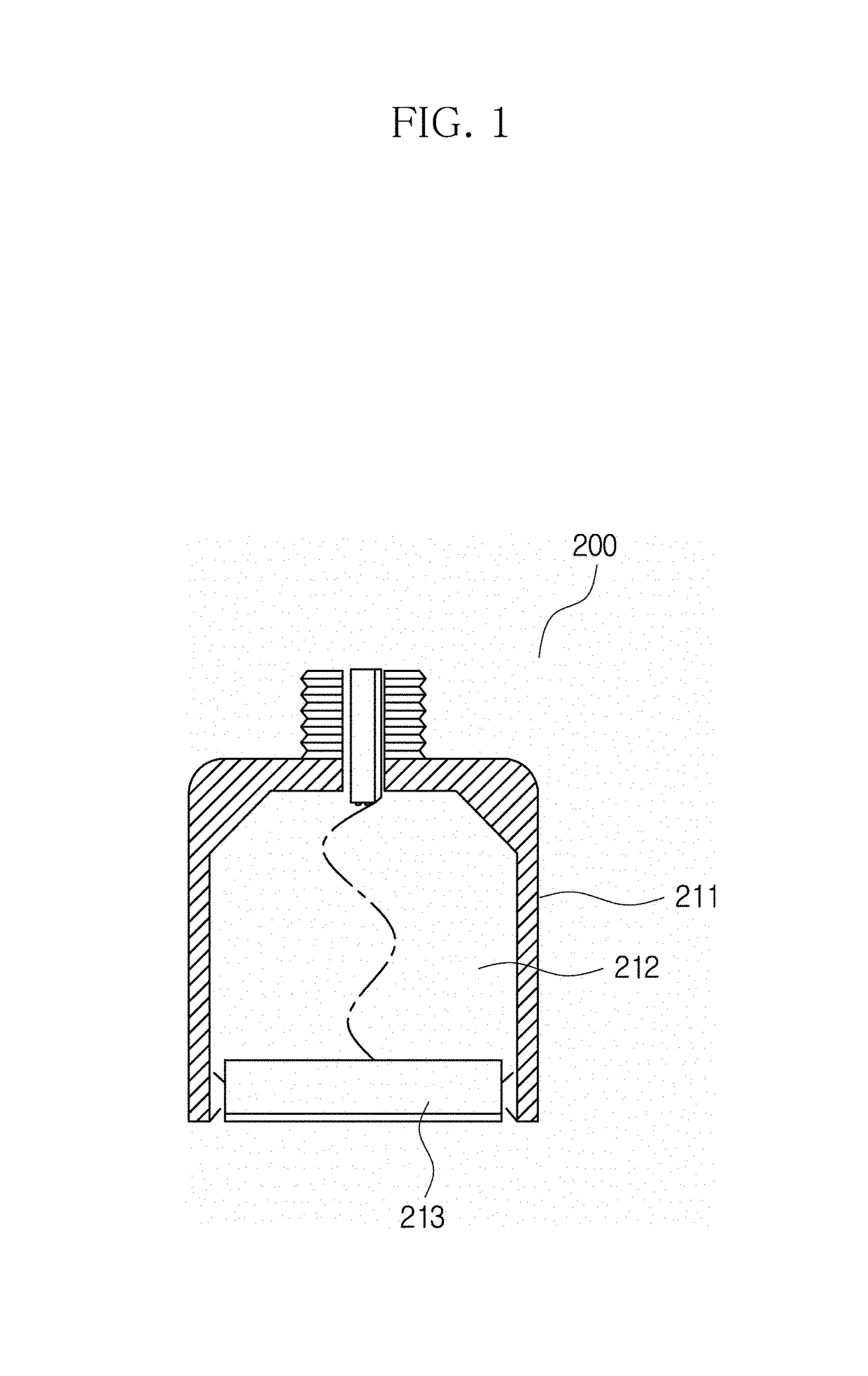
[0055]The ultrasonic stimulation device according to this embodiment is an ultrasonic stimulation device for carrying out surgery to apply ultrasonic stimulation to the brain of a subject, and includes an ultrasonic transducer 200 to emit a focused ultrasound 214 focused to a focal point (e.g. target point) 215, and a guide framework 100 to position the ultrasonic transducer 200.

[0056]FIG. 7A is a rear perspective view of the guide framework 100.

[0057]Referring to FIGS. 6 and 7A, the guide framework 100 includes...


PUM


Abstract

A guide framework for positioning an ultrasonic transducer which emits a focused ultrasound to a target point in carrying out surgery to apply ultrasonic stimulation to a subject's brain, includes a body in a shape of a mask that is laid on the subject's face, and a positioning hole formed through an inner surface and an outer surface of the mask body, the positioning hole into which the ultrasonic transducer is inserted, wherein the inner surface of the mask body is formed to conform a facial contour of the subject, and when the guide framework is laid on the subject's face and the ultrasonic transducer is disposed at the positioning hole, the position of the target point is naturally disposed at a preset stimulation site of the brain. An ultrasonic stimulation device includes an ultrasonic transducer and the guide framework for positioning the ultrasonic transducer.

Description

CROSS-REFERENCE TO RELATED APPLICATION[0001]This application claims priority to Korean Patent Application No. 10-2016-0113949, filed on Sep. 5, 2016, and all the benefits accruing therefrom under 35 U.S.C. § 119, the contents of which in its entirety are herein incorporated by reference.BACKGROUND1. Field[0002]The present disclosure relates to an ultrasonic stimulation device, and more particularly, to a guide framework for positioning an ultrasonic transducer in carrying out surgery to apply ultrasonic stimulation to the brain of a subject, and an ultrasonic stimulation device using the same.DESCRIPTION ABOUT NATIONAL RESEARCH AND DEVELOPMENT SUPPORT[0003]This study was supported by the Brain Science Source Technology Development Project of Ministry of Science, ICT and Future Planning, Republic of Korea (Development of MRI-based image-guided brain stimulation control system for internet game addiction treatment, Project No. 1711029671) under the Korea Institute of Science and Techn...

Claims


Application Information

Patent Timeline
Patent Type & Authority Applications(United States)
IPC IPC(8): A61N7/00
CPCA61N7/00A61N2007/0026A61N2007/006A61N2007/0078A61N2007/0082A61B90/11A61B90/10A61B90/18A61B2090/502A61B5/055A61B5/4884
Inventor KIM, HYUNG MINYOUN, INCHANKIM, SEUNG-JONGCHOI, JUNHYUKBAEK, HONGCHAEJUNG, CHAN YUL
Owner KOREA INST OF SCI & TECH
Learn More