
Charging device of moving robot and control method thereof

Active Publication Date: 2018-03-08
LG ELECTRONICS INC
View PDF9 Cites 10 Cited by
  • Summary
  • Abstract
  • Description
  • Claims
  • Application Information

AI Technical Summary

Benefits of technology

The technical effects of this patent are to provide a charging device for a robotic lawn mower that can keep the lawn present while supplying power to the mower smoothly. Additionally, the device can minimize the area shared by the charging stand and the mower's operation region.

Problems solved by technology

However, the two types of lawn mower are cumbersome in that a human should directly operate them.
In particular, in the modern busy daily lives, it is difficult for users to directly operate a lawn mower to mow the lawn of the ground (or a yard), users mostly employ a worker to mow the lawn, incurring cost for employment.

Method used


Image

  • Charging device of moving robot and control method thereof
  • Charging device of moving robot and control method thereof
  • Charging device of moving robot and control method thereof

Examples


Embodiment Construction

[0044]Hereinafter, the embodiments of the present invention will be described with reference to the accompanying drawings, in which like numbers refer to like elements throughout although the embodiments are different, and a description of the like elements a first embodiment will be used for those of the different embodiment. In the following description, usage of suffixes such as ‘module’, ‘part’ or ‘unit’ used for referring to elements is given merely to facilitate explanation of the present invention, without having any significant meaning by itself. In describing the present invention, if a detailed explanation for a related known function or construction is considered to unnecessarily divert the gist of the present invention, such explanation has been omitted but would be understood by those skilled in the art. The accompanying drawings of the present invention aim to facilitate understanding of the present invention and should not be construed as limited to the accompanying d...


PUM


Abstract

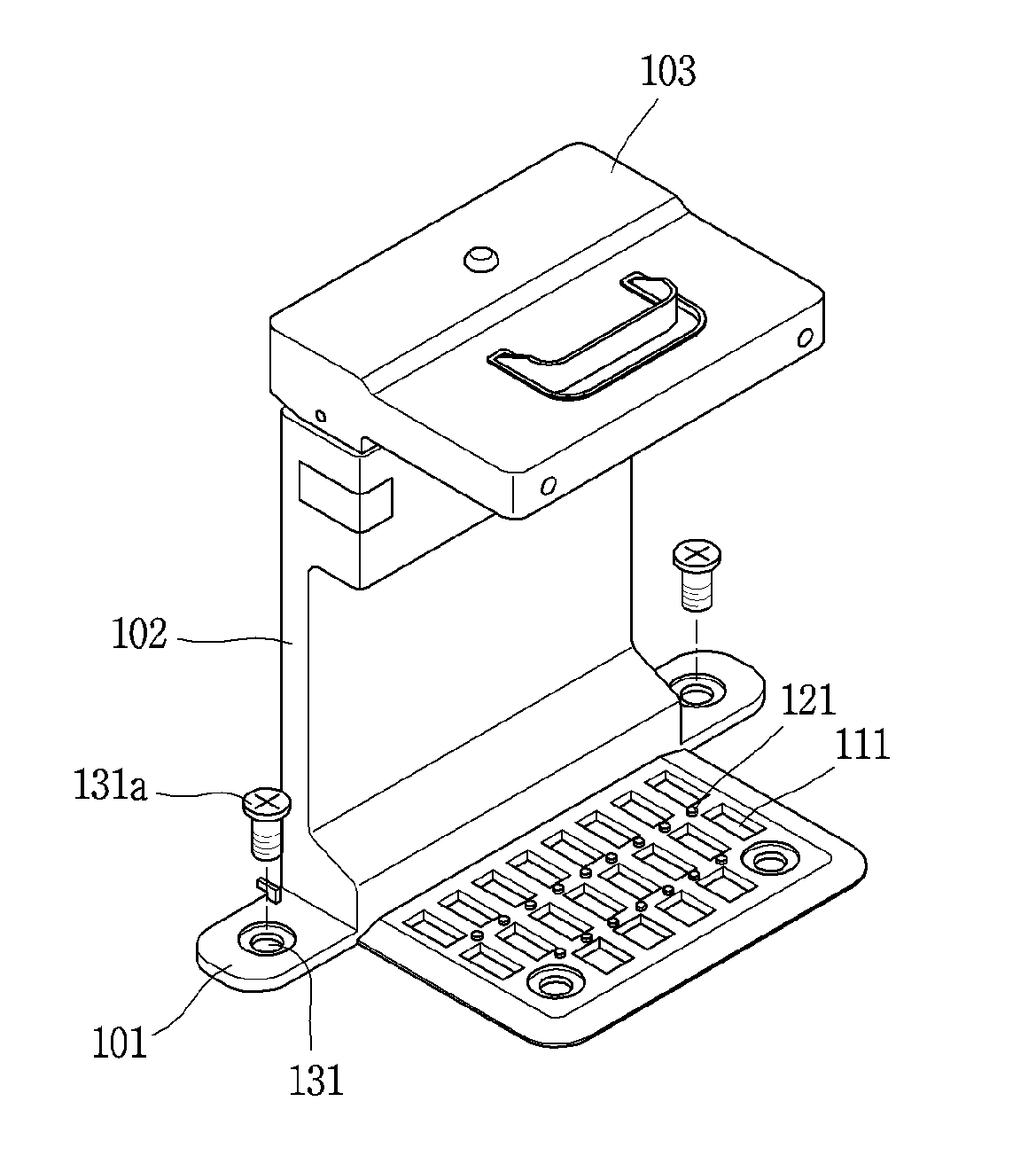
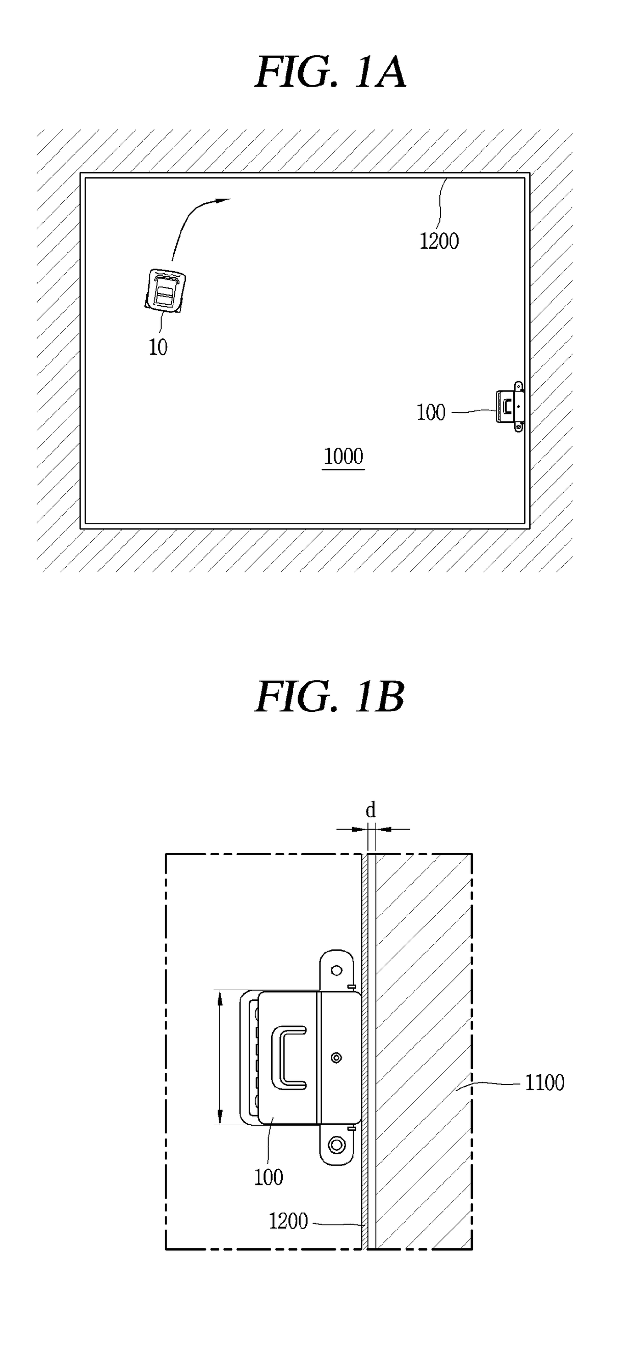
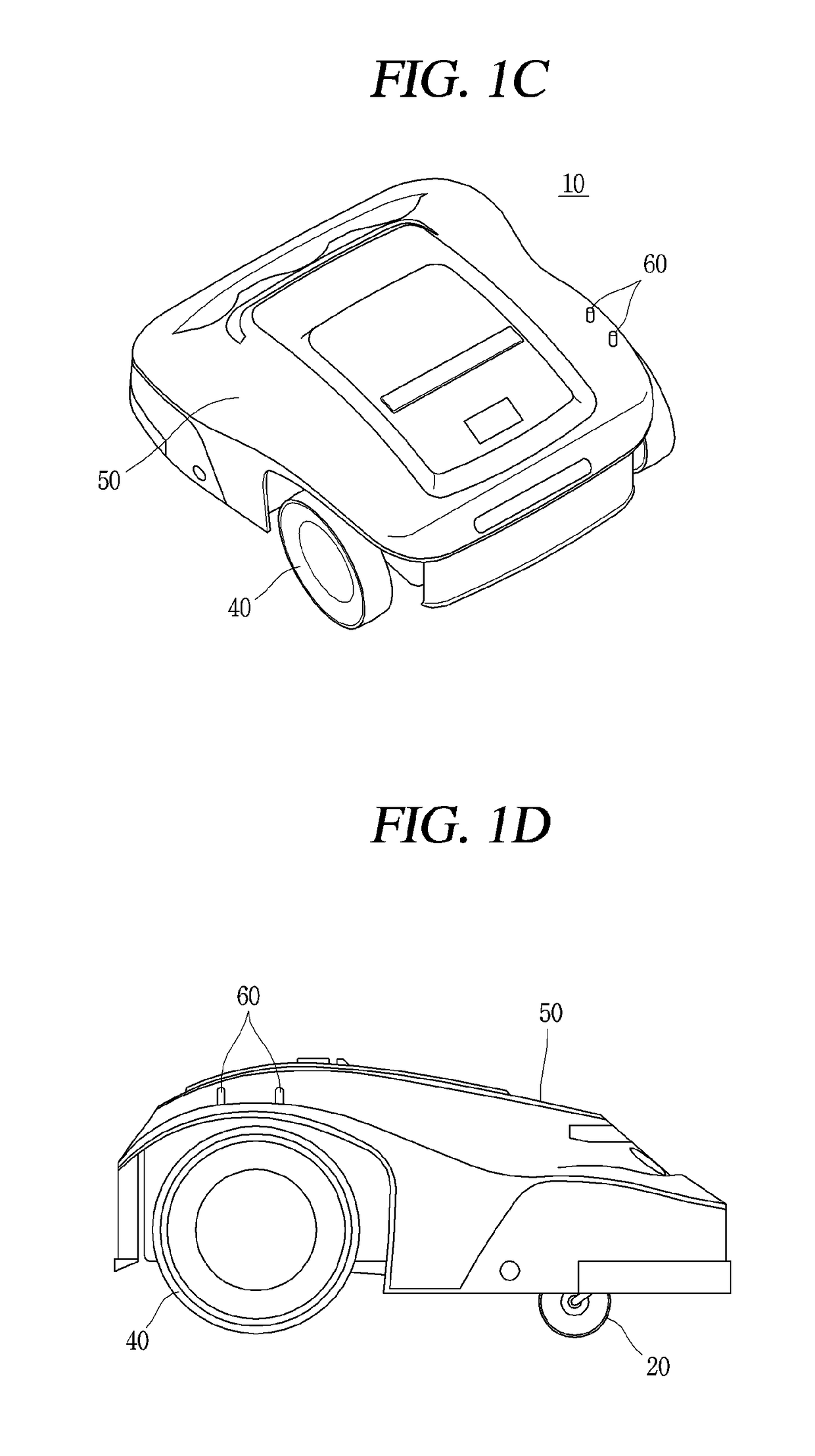
A charging device of a robotic lawn mower includes a bottom part installed in a partial region of an operation region of the robot, a support part coupled to the bottom part and positioned on a side of a main body of the robot when the robot is being charged, and a terminal part coupled to the support part and positioned above the main body of the robot when the robot is being charged, wherein the bottom part is formed such that only any one of a plurality of wheels of the robot is mounted thereon when the robot is being charged.

Description

CROSS-REFERENCE TO RELATED APPLICATION[0001]Pursuant to 35 U.S.C. § 119(a), this application claims the benefit of an earlier filing date of and the right of priority to U.S. Provisional Application No. 62 / 383,507, filed on Sep. 5, 2016, the content of which is incorporated by reference herein in their entirety.BACKGROUND OF THE INVENTION1. Field of the Invention[0002]The present disclosure relates to a charging device of a moving robot and a control method thereof, and particularly, to a charging device of a robotic lawn mower moving on an inner side of a boundary wire and a control method thereof.2. Background of the Invention[0003]A lawn mower is a machine for cutting grass that grows in a yard of a house, a playing field, and the like. The lawn mower may be classified as a home lawn mower used in houses and a tractor lawn mower used in a large playing field or a large farm.[0004]The home lawn mower includes a walk-behind type lawn mower which requires a human to walk behind and ...

Claims


Application Information

Patent Timeline
IPC IPC(8): A01D34/00G05D1/02B60L11/18H02J7/00
CPCA01D34/001G05D1/0276A01D34/008B60L11/1816B60L11/182G05D1/0225G05D2201/0208A01D2101/00A01D34/78H02J7/0042B60L53/14B60L53/12B60L53/31B60L53/35H02J7/0045Y02T10/70Y02T90/12Y02T10/7072Y02T90/14H02J2310/22H02J3/322
Inventor SONG, HYUNSUPNAM, DONGKYUNWOO, JONGJIN
Owner LG ELECTRONICS INC
Learn More