
Fuse resistor and method of manufacturing the same

a fuse resistor and resistor technology, applied in resistors, resistor details, electrical equipment, etc., can solve problems such as fuse resistor fragments, and achieve the effect of simple structur

Inactive Publication Date: 2018-02-15
SMART ELECTRONICS CO LTD
View PDF6 Cites 7 Cited by
  • Summary
  • Abstract
  • Description
  • Claims
  • Application Information

AI Technical Summary

Benefits of technology

The present invention provides a fuse resistor that has a simple structure and can be made smaller as an integrated structure of a thermal fuse and lead wire. The method of manufacturing this fuse resistor is also provided. The technical effects of this invention include a simplified manufacturing process and a smaller size of the fuse resistor.

Problems solved by technology

In addition, when the fuse blows, fragments occur in the fuse resistor.

Method used


Image

  • Fuse resistor and method of manufacturing the same
  • Fuse resistor and method of manufacturing the same
  • Fuse resistor and method of manufacturing the same

Examples


Embodiment Construction

[0035]Hereinafter, the embodiments of the present invention will be described in detail with reference to the accompanying drawings.

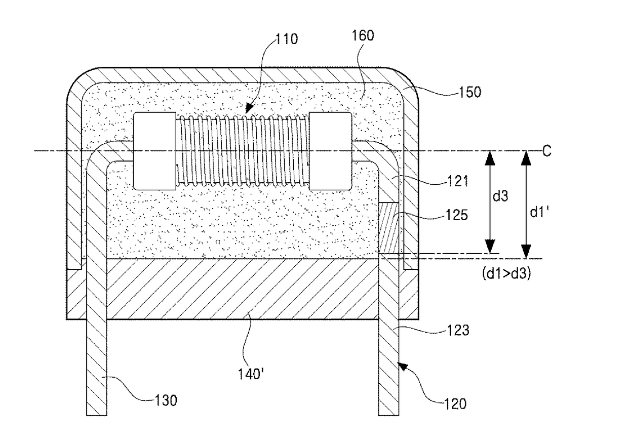
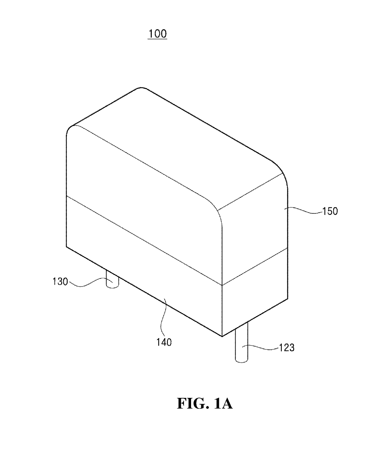
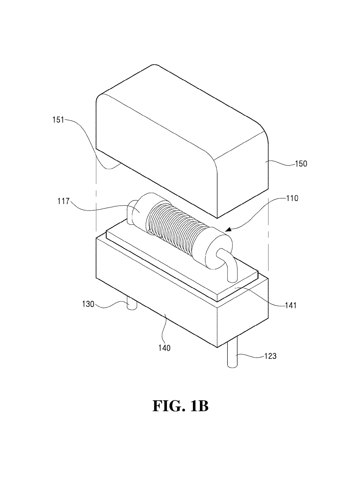
[0036]Referring FIGS. 1A, 1B, 2A, 2B, 2C, 2D, and 3, a fuse resistor, which is designated by reference numeral “100” according to the present invention, may be provided to be adopted in an electric circuit of an electric product. The fuse resistor may include a resistor 110, a fusing lead wire 120 and a lead wire 130 coupled to both ends of the resistor 110, respectively, a lower molding unit 140 mold-injected in the state that a part of the fusing lead wire 120 and a part of the lead wire 130 are spaced apart a certain distance from each other in an inserted manner, an upper casing 150 coupled to the lower molding unit 140, and a filler 160 filling an inner space of the upper casing 150.

[0037]Upon applying overcurrent, the resistor 110 radiates heat such that a thermal fuse 125 mounted at the fusing lead wire 120 may blow. As illustrated in FIG. 2B, fo...


PUM


Abstract

Provided are a fuse resistor and a method of manufacturing the same, more particularly, are a fuse resistor mounted at an electric circuit of an electronic product to prevent the electronic product from breaking down due to inrush current, increase of internal temperature, and continuous overcurrent, and a method of manufacturing the same. The fuse resistor is capable of simplifying an assembly process by coupling a thermal fuse and a lead wire in a modularized manner and by fixing a fusing lead wire to the lead wire in an integrated manner to form a lower molding unit, and a method of manufacturing the same. The fuse resistor has a simple structure and is capable of being miniaturized as an integrated structure of the thermal fuse and the lead wire is inserted, and a method of manufacturing the same.

Description

BACKGROUND OF THE INVENTIONField of the Invention[0001]The present invention relates to a fuse resistor and a method of manufacturing the same, and more particularly, to a fuse resistor mounted at an electric circuit of an electronic product to prevent the electronic product from breaking down due to inrush current, increase of internal temperature, and continuous overcurrent, and a method of manufacturing the same.Description of the Related Art[0002]Generally, in an electric circuit of a large electronic product such as an LCD TV, or a PDP TV, a protector such as a thermal fuse resistor for protecting the electric circuit is provided at an input terminal. Thereby, the protector prevents the electronic product from breaking down due to inrush current, increase of internal temperature, and continuous overcurrent, which are generated when powered on.[0003]Such a fuse resistor includes a resistor, a thermal fuse, a lead wire connected between the resistor and the thermal fuse.[0004]In ...

Claims


Application Information

Patent Timeline
Patent Type & Authority Applications(United States)
IPC IPC(8): H01H85/048H01H85/18H01H85/00H01H85/165H01C1/14H01C3/20
CPCH01H85/048H01C1/14H01C3/20H01H85/18H01H85/0047H01H85/165H01H85/0013H01C1/028H01C1/144H01C17/02H01H85/143
Inventor KANG, DOO WONKIM, HYUN CHANGMUN, HWANG JESHIN, A LAM
Owner SMART ELECTRONICS CO LTD
Learn More