Valve rake and mount for surgical retractor

a retractor and valve rake technology, applied in the field of valve rake and mount for surgical retractors, can solve the problems of large mechanism that consumes needed space in the surgical area, inconvenient and time-consuming, and may require significant skill in obtaining the desired position, so as to achieve convenient setting of the mandated position, maintain the available space for surgical access, and improve the effect of accuracy

Inactive Publication Date: 2018-02-15
TERUMO CARDIOVASCULAR SYST CORP
View PDF0 Cites 9 Cited by
  • Summary
  • Abstract
  • Description
  • Claims
  • Application Information

AI Technical Summary

Benefits of technology

The invention is a medical device that uses a flexible joint with a malleable shaft. It allows for easy adjustment to a specific position using just one locking dial. The device is compact and maintained space for surgical access. The technical effect of this invention is fast, simple, and secure adjustment in a secure and efficient manner.

Problems solved by technology

However, manipulation to obtain the desired position may require significant skill and may be inconvenient and time consuming.
Furthermore, the size / thickness and length requirements for flexible structures that can also provide sufficient stability for the desired holding characteristics has also resulted in large mechanisms that consume needed space within the surgical area, especially since several valve rakes may be needed simultaneously.

Method used


Image

  • Valve rake and mount for surgical retractor
  • Valve rake and mount for surgical retractor
  • Valve rake and mount for surgical retractor

Examples


Embodiment Construction

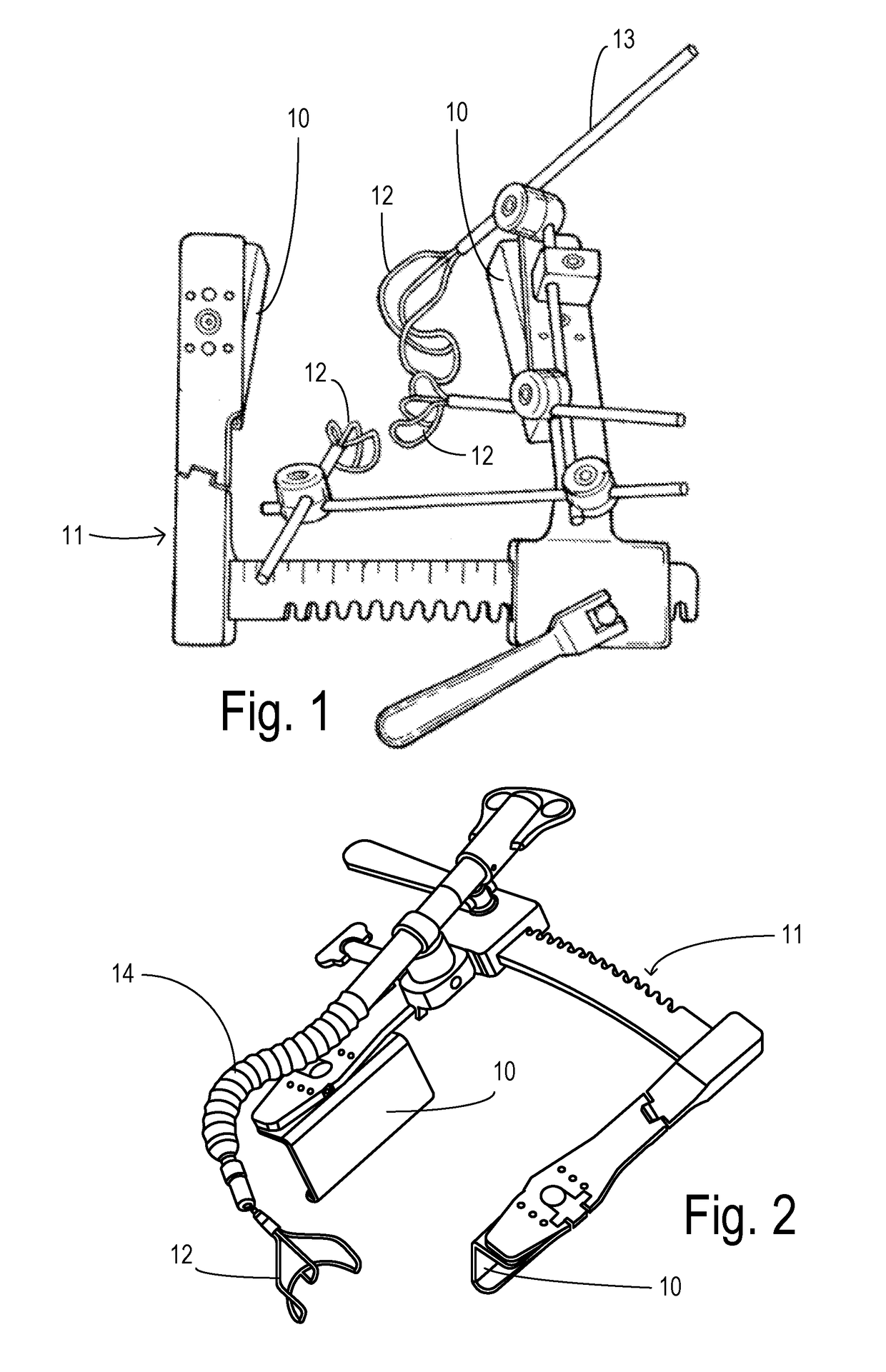
[0020]FIGS. 1 and 2 show prior art sternal retractors with spaced blades 10 carried by an adjustable frame 11. Valve rakes 12 are carried by rigid rods 13 or bendable rod 14, respectively. Each may have an adjustable suspension mechanism.

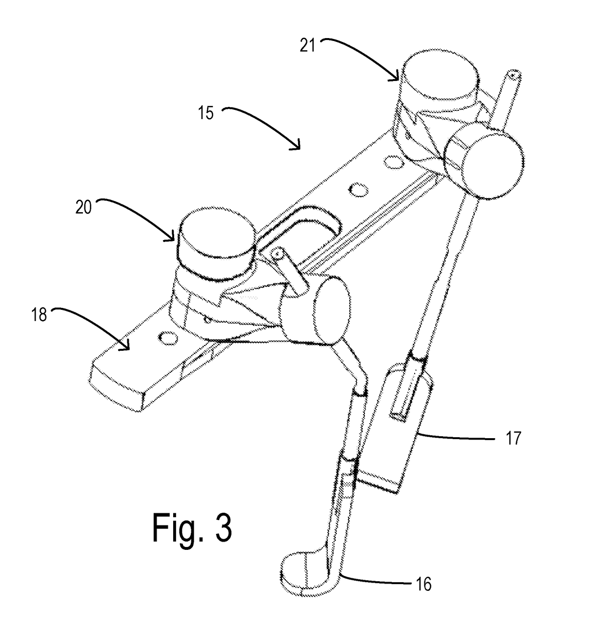
[0021]FIG. 3 shows a first embodiment of the invention wherein retractor rake fingers 16 and 17 are attached to a retractor slide 18 by mounting mechanisms 20 and 21, respectively, which are constructed as identical articulating joints. Slide 18 is configured to attach to a frame of a sternal retractor system or to other fixed structures depending on the particular surgical procedure for which it may be used. Mechanism 20 will be described in greater detail below.

[0022]FIG. 4 shows an exploded view wherein mechanism 20 is comprised of a thumb screw 22 having a threaded shaft 23 which matches any of threaded receiving holes 24 in slider 18. Slider 18 can be fixed to the frame of the sternal retractor in any convenient manner known to the art. Threade...


PUM


Abstract

A mounting mechanism for use with surgical retractor rakes mounts to a fixed frame at an edge of a surgical site to that the rake can be conveniently configured into position with simple manual adjustments. A valve rake finger is arranged on the end of a shaft. An articulating joint having a movable plunger with a shaft carriage and a pressing mechanism selectably engages the plunger to lock the shaft in a desired position. A slider plate receives the articulating joint and attaches to a fixed frame.

Description

CROSS REFERENCE TO RELATED APPLICATIONS[0001]This application claims priority to provisional application Ser. No. 62 / 372,334, filed on Aug. 9, 2016, which is incorporated herein by reference in its entirety.BACKGROUND OF THE INVENTION[0002]The invention applies to heart surgery, especially heart valve repair or replacement. In the case of a damaged valve, open heart surgery is typically conducted to replace or repair the valve through the aorta. For this operation, operating room assistant personnel may use a valve rake to keep the valve round and stable for suturing.[0003]Besides manually holding the valve rake, fixed mechanisms have been used to suspend a rake in a desired position. During cardiac surgery, a sternal retractor is typically mounted over the patient carrying retractor blades to separate overlying tissues to allow access to a surgical site. The frame of the sternal retractor has been used to support mechanical rakes, as in U.S. Pat. No. 5,772,583, for example.[0004]To...

Claims


Application Information

Patent Timeline
Patent Type & Authority Applications(United States)
IPC IPC(8): A61B17/02
CPCA61B2017/0237A61B17/0206A61B2017/00477A61B2017/00946
Inventor TSUBOUCHI, TAKESHI
Owner TERUMO CARDIOVASCULAR SYST CORP
Why Eureka
Try Eureka