
Subterranean Formation Shock Fracturing Charge Delivery System

a charge delivery system and subterranean technology, applied in the direction of explosive charges, fluid removal, borehole/well accessories, etc., can solve the problems of wasting precious liner length, affecting the depth, direction and distance control, and unpredictable irregular thin sheet-like jets. achieve the effect of facilitating the depth, direction and distance control, and reducing the volume of energy resources

Inactive Publication Date: 2018-02-01
INNOVATIVE DEFENSE
View PDF0 Cites 44 Cited by
  • Summary
  • Abstract
  • Description
  • Claims
  • Application Information

AI Technical Summary

Benefits of technology

[0024]The present invention uses shaped charge devices in the recovery of subsurface minerals and substances, which maximizes the development, production and capture of energy resources over traditional hydraulic fracturing (HF) techniques. The present invention and system reduces the steps in the perforating and fracturing operations of the mineral bearing formation compared to traditional methods, which reduces the operation time and costs incurred in the recovery, capture, production and delivery of energy resources. The present invention achieves those objectives by controlling the direction and distance of charge detonation around the well bore or well casing.
[0025]The present invention is a subterranean (non-hydraulic) shock fracturing system and process for fracturing oil and gas bearing formations, and the present invention delivers predetermined amounts of precisely placed explosive charges into the formation surrounding a bore hole or well casing. By precision controlling the delivery of predetermined explosive charges, the present invention makes possible a precision-controlled delivery of a measured quantity of explosive into a subterranean oil or gas bearing formation with the detonation of said explosive in order to fracture the formation in an intended and directionally controlled local vicinity.
[0026]The predetermined amounts of charges in the present invention produce large diameter deep penetrations into the formation; and, by coupling to the rock concussively fractures, the formation in the vicinity of this directionally and distance controlled explosive charge will increase permeability in a desired portion of the rock or formation strata. Secondary and tertiary charges can also be loaded and exploded using the present invention to increase the depth of the primary holes, enlarge the perforations, fracture the mineral bearing formation, and maximize the production, recovery and delivery of target resources from the formation. The ability to selectively “reshoot” lateral perforation holes into new wells (or underperforming old wells) with shaped charges using predetermined amounts of explosive will also improve formation communication, unlike current hydraulic fracturing (HF) methods or any previous efforts using large amounts of explosive.

Problems solved by technology

These line charge devices are collapsed from only two opposing directions producing a very irregular thin sheet-like jet that is unpredictable in its penetrating ability due to the lack of a simultaneous initiation along the apex of the line explosive.
These line charges are limited in the thickness or toughness of the target they can address and are mainly used for light walls.
The small diameter of the interrupter does not form a large enough diameter jet to produce a full caliber hole or to hold its annular shape after it separates from the interrupter; the jet will converge into a rod and some of the precious liner length is wasted.
The outer wall is converging whereas the inner wall, with much less mass, is diverging; the same problem exists with the explosive quantities driving each wall of the liner.
These line charges are very inefficient and difficult to initiate in a manner conducive to achieving their full potential.
Additionally, sometimes users such as police or firefighters are badly injured or killed trying to use these awkward and clumsy devices.
This inconsistency causes many fracturing operation issues, and small hole size limits product flow into and from the formation; if too small, the perforation will get fouled with debris and can stop flowing altogether.
Some effort has been made with placing a conventional shaped charge ahead of the projectile in order to create a pilot hole in the rock; however, only a small gain in depth of penetration is achievable with this method because of the very small hole diameter produced by a conventional shaped charge.
There have been many efforts throughout the years to hydraulically fracture resource bearing formations, but these prior efforts have been unable to penetrate more than a few feet beyond the main well bore.
Although hydraulic fracturing of oil and gas bearing formations has been used for many decades, this process does not maximize the capture of valuable energy resources and it leaves valuable resources behind in the formation.
There are many problems associated with these hydraulic fracturing and the use of hydraulic fracturing fluids.
First, the hydraulic fracturing fluids deposit propends in the well perforations that initially maintain an open flow of fluids in the formation, but these propends eventually grind down to powder and close up the formation fluid flow.
This clogging and closure in the formation fluid flow causes production inefficiencies, which cannot be remedied by present hydraulic fracturing (HF) techniques.
Second, hydraulic fracturing (HF) can only create fracture lines that are not controlled by depth or direction, which means traditional hydraulic fracturing (HF) techniques cannot be regulated to target the highest resource bearing portion of a formation.
Third, traditional hydraulic fracturing (HF) techniques are very costly procedures, which consume approximately 80% of total well completion costs. The monetary costs makes traditional perforating techniques and hydraulic fracturing almost monetarily prohibitive at today's oil and gas prices.
Fourth, because hydraulic fracturing (HF) has no ability to be directional or depth controlled, the hydraulic fluids flow along formation fracture lines that follow planes of natural weaknesses in the formation material. This flow of high pressure hydraulic fracturing fluids into natural weaknesses in formation materials and formation fracture lines (e.g. faults) is accused of creating significant negative environmental impact and raised criticism and concerns about existing hydraulic fracturing (HF) techniques from the federal Environmental Protection Agency, as well as some state environmental agencies and environmentalists. Hydraulic fracturing (HF) techniques have been viewed under tighter and tighter scrutiny by these agencies and environmental advocates.
Previous efforts of energy recovery using traditional hydraulic fracturing techniques have not been successful or productive at increasing the production of energy resources from substrate formations around a borehole.
In fact, the above problems will, in time, make the hydraulic fracturing (HF) operations more expensive to conduct (e.g. cost prohibitive), as well as less desirable and less practical, not to mention evoking environmental claims regarding the introduction of hydraulic fluids into fault areas of the surrounding formations, which individually or cumulatively may prevent and prohibit such uncontrolled and undirected hydraulic fracturing (HF) procedures.

Method used


Image

  • Subterranean Formation Shock Fracturing Charge Delivery System
  • Subterranean Formation Shock Fracturing Charge Delivery System
  • Subterranean Formation Shock Fracturing Charge Delivery System

Examples


Embodiment Construction

[0064]The present invention is a subterranean (non-hydraulic) shock fracturing system and process for fracturing oil and gas bearing formations, and the present invention delivers predetermined amounts of precisely placed explosive charges into the formation surrounding a bore hole or well casing. The present invention uses shaped charge devices in the recovery of subsurface minerals and substances, which maximizes the development, production and capture of energy resources over traditional hydraulic fracturing (HF) techniques. The present invention achieves those objectives by controlling the direction and distance of charge detonation around the well bore or well casing.

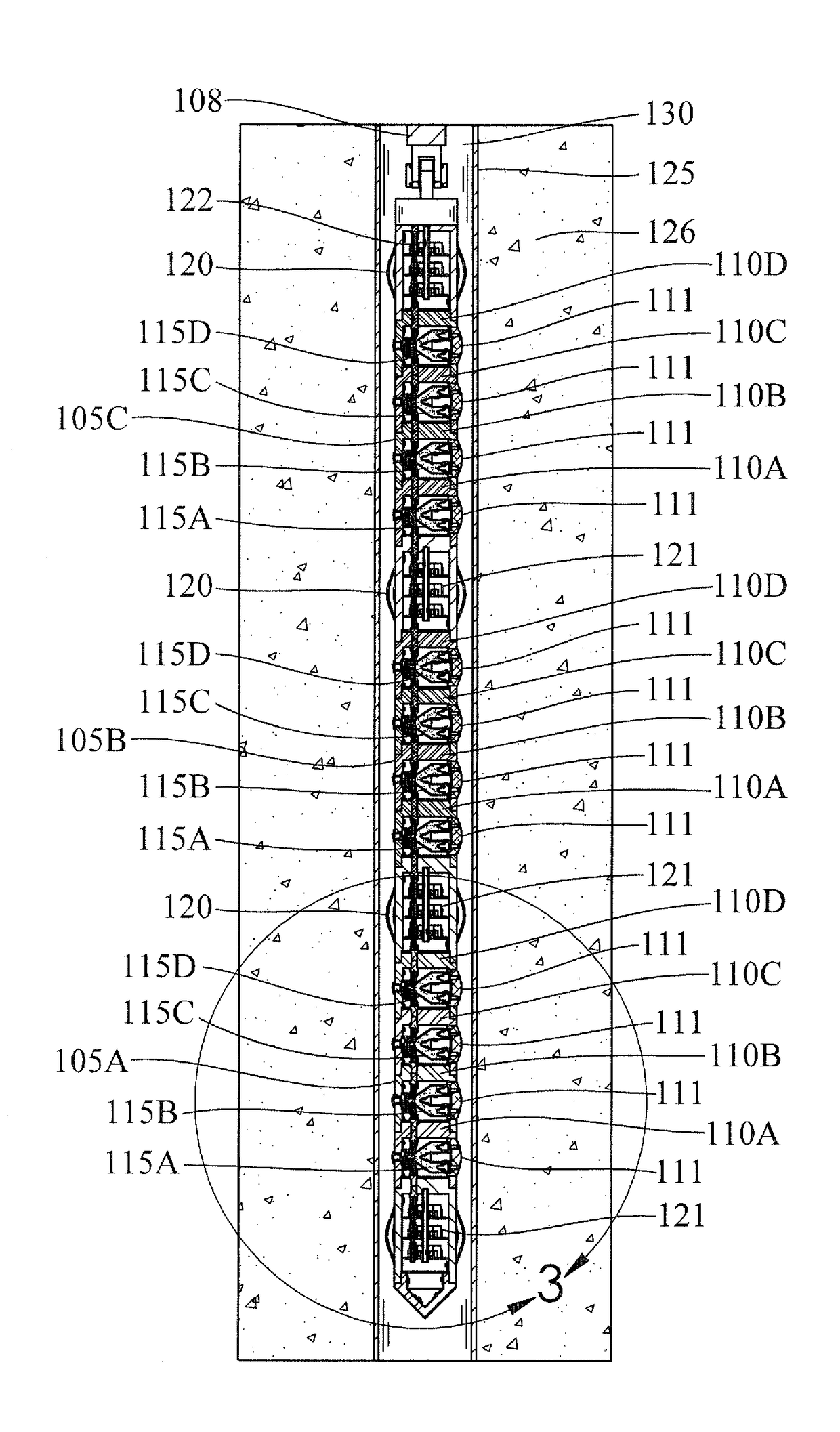
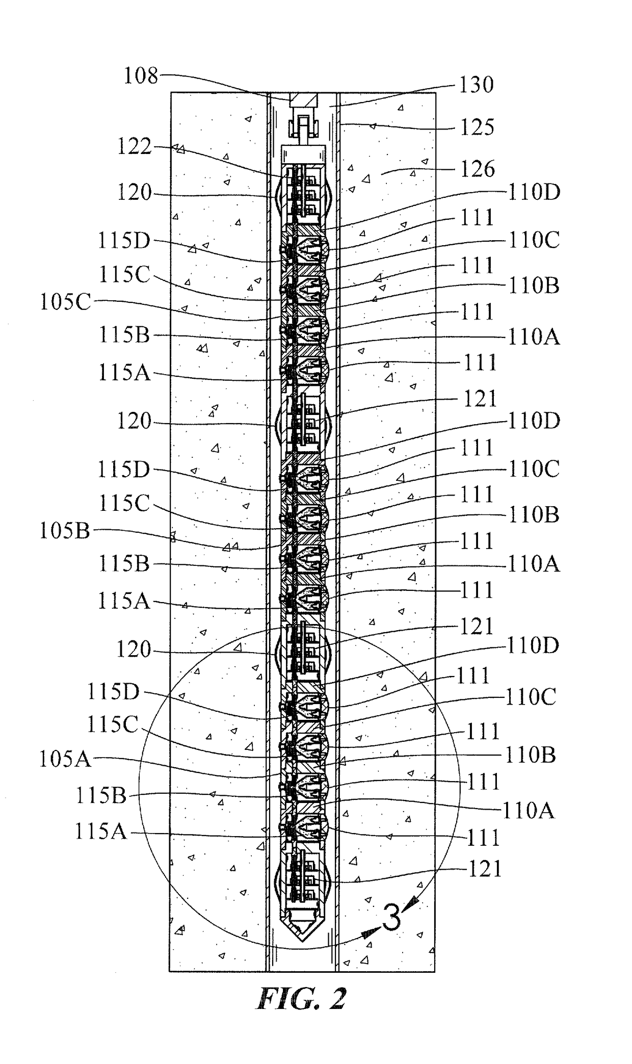
[0065]FIG. 1 depicts the present invention, which can be called a Select Fire Gun System (SFGS) 100, is shown prior to explosive charge initiation in a subterranean formation 126 inside a well borehole 130 and a well casing 125. The explosive charges in the present invention SFGS system consists of three primary se...


PUM

PropertyMeasurementUnit
velocityaaaaaaaaaa
diameteraaaaaaaaaa
diameteraaaaaaaaaa

Abstract

This invention is a subterranean (non-hydraulic) shock fracturing system and process for fracturing oil and gas bearing formations. The system delivers small amounts of precisely placed explosive charges into the formation. These charges produce large diameter deep penetrations and by coupling to the rock concussively fracture the formation in the vicinity increasing permeability in the rock or strata. Shock fracturing (SF) is far more efficient than hydraulic fracturing (HF), SF fractures radially across all strata and leaves no part of the volume addressed un-permeated. The objective of the system is to efficiently increase permeability of the formation by directionally controlled concussive shattering of the rock around the epicenter of the detonation of the explosive charge deposited in the formation. This invention makes possible the delivery of measured quantities of explosive deep into a subterranean oil or gas bearing formation and detonate said explosive in order to fracture the formation in the local vicinity.

Description

RELATED APPLICATION DATA[0001]This application is related to Provisional Application Ser. No. 62 / 368,800 filed on Jul. 29, 2016, and priority is claimed for this earlier filing under U.S.C. §119(e). The Provisional patent application is also incorporated by reference into this application.TECHNICAL FIELD OF INVENTION[0002]The technical field of the present invention relates to using shaped charge devices in the recovery of subsurface minerals and substances, which directly relates to the development of energy resources.BACKGROUND OF INVENTION[0003]As Donald R. Kennedy described in “The History of Shaped Charges,” the concept of shaping an explosive charge to focus its energy was known as far back as 1792. In 1884, Max von Forester conducted experiments in Germany showing that an explosive charge with a hollow cavity will focus the explosive energy and produce a collimated jet of high speed gasses along the longitudinal axis of the cavity. When this cavity is lined with a ductile met...

Claims


Application Information

Patent Timeline
Patent Type & Authority Applications(United States)
IPC IPC(8): C09K8/62C09K8/80E21B43/26C09K8/70
CPCC09K8/62C09K8/70E21B43/00E21B43/26C09K8/00C09K8/80E21B43/117E21B43/119F42B1/02F42B1/028F42B3/02
Inventor COLLIER, NICHOLASFLATT, DAVID SHAWN
Owner INNOVATIVE DEFENSE
Learn More