
Wind power generating equipment, operation method thereof, and wind farm

Inactive Publication Date: 2018-01-11
HITACHI LTD
View PDF1 Cites 2 Cited by
  • Summary
  • Abstract
  • Description
  • Claims
  • Application Information

AI Technical Summary

Benefits of technology

The invention allows for the wind power generating equipment to control its power output quickly in response to changes in voltage. This ensures that the wind power system can continue operating even during abnormal situations.

Problems solved by technology

However, when a system voltage is instantaneously reduced due to a lightning strike or the like, a phenomenon of collective cutoff of the wind power generating equipment from a system occurred in the past.

Method used


Image

  • Wind power generating equipment, operation method thereof, and wind farm
  • Wind power generating equipment, operation method thereof, and wind farm
  • Wind power generating equipment, operation method thereof, and wind farm

Examples


example 1

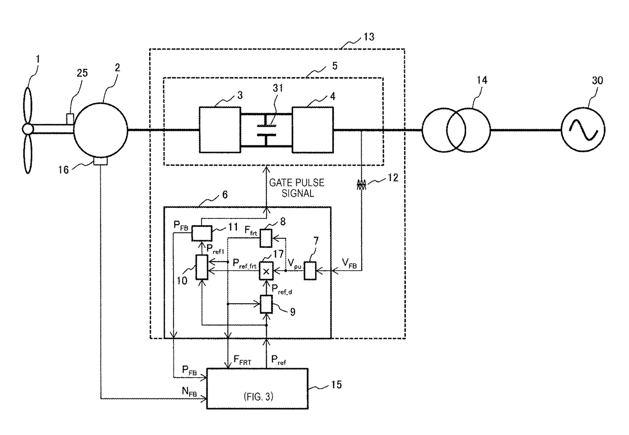
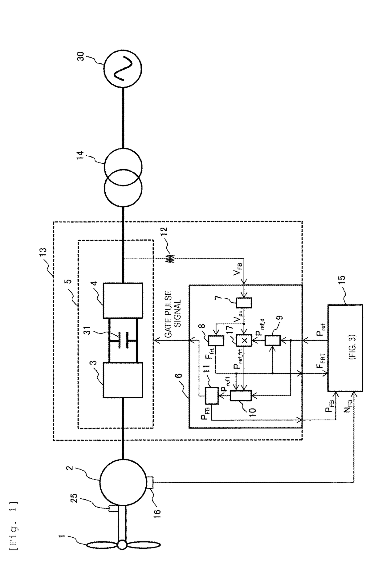
[0017]FIG. 1 is a diagram illustrating a configuration of wind power generating equipment according to Example 1 of the invention. In FIG. 1, a main body of the wind power generating equipment is configured to include a blade 1, a generator 2, and a power conversion system 13. In addition, an output of the generator 2 is interconnected from the power conversion system 13 via a step-up transformer 14 to a power system 30.

[0018]The power conversion system 13 is configured to include a power converter 5 and a power converter controller 6. The power converter 5 is configured to include a DC capacitor 31 disposed between a generator-side power converter 3 and a system-side power converter 4. The generator-side power converter 3 converts AC power of the generator 2 as a synchronous generator into DC power and the system-side power converter 4 converts DC power of the generator-side power converter 3 into AC power.

[0019]The generator-side power converter 3 and the system-side power convert...

example 2

[0043]Next, differences of Example 2 from Example 1 of the invention will be mainly described. In Example 1, the generator 2 is the synchronous generator, and the power conversion system 5 has a configuration of a full converter; however, the generator 2 is a secondary excitation winding induction generator, and the power conversion system 5 is a secondary excitation type power conversion system as illustrated in FIG. 4 in Example 2.

[0044]In Example 2, in order to control a frequency and a magnitude of an excitation current applied to a rotor of the secondary excitation winding induction generator 26, the power conversion system 5 is replaced with a secondary excitation type power conversion system 29 and is configured to include a rotor-side power converter 27 that converts AC power of a rotor into DC power and a system-side power converter 28 that converts DC power of the rotor-side power converter into AC power. Also in Example 2, in the power converter 5 similar to Example 1, th...


PUM


Abstract

Wind power generating equipment includes: a generator that is driven by a blade which rotates by receiving the wind; a power converter that converts an electric output of the generator such that the output is interconnected with an electric power system; a power converter controller that controls the power converter; and a wind turbine control board that transmits, to the power converter controller, an active power command value that is used as a command value of the electric output which is transmitted from the power converter. The power converter controller controls the output of the power converter in response to an active power command value, depending on a reduction amount of a system voltage when instantaneous reduction occurs in the system voltage interconnected with the wind power generating equipment. This permits stable operation of the wind power generating system when instantaneous voltage reduction occurs such as during a system abnormality.

Description

TECHNICAL FIELD[0001]The present invention relates to wind power generating equipment, operation method of the wind power generating equipment, and a wind farm, particularly, to wind power generating equipment, operation method thereof, and a wind farm which are suitable during voltage reduction and power return of an interconnected system.BACKGROUND ART[0002]Wind power generating equipment is an environment-friendly power generation method without emission of dioxide and thus, recently, the wind power generating equipment has been introduced. However, when a system voltage is instantaneously reduced due to a lightning strike or the like, a phenomenon of collective cutoff of the wind power generating equipment from a system occurred in the past. Therefore, it is mandatory for the wind power generating equipment to have a fault ride through (FRT) function of continuing an operation even when instantaneous voltage reduction occurs during an occurrence of system abnormality.[0003]PTL 1...

Claims


Application Information

Patent Timeline
IPC IPC(8): H02P9/10F03D7/02
CPCH02P9/102F03D9/25F05B2270/1071H02P9/10H02P2101/15F03D7/0272H02J3/48H02J2300/28H02J3/381H02J3/46Y02E10/72Y02E10/76
Inventor ITOH, YUTASAKAMOTO, KIYOSHIMEGURO, HIKARUFUJII, TOMOHIRO
Owner HITACHI LTD
Learn More