Eureka AIR delivers breakthrough ideas for toughest innovation challenges, trusted by R&D personnel around the world.

Laser Sensor Stimulator

a stimulator and laser sensor technology, applied in the direction of distance measurement, instruments, lighting support devices, etc., can solve the problems of low validation and direct illumination during flight, large laboratory and ground characterization and testing, and inability to accurately detect the position of the laser sensor, etc., to achieve the effect of reducing the risk of laser damag

Active Publication Date: 2018-01-04
THE UNITED STATES OF AMERICA AS REPRESETNED BY THE SEC OF THE AIR FORCE
View PDF2 Cites 1 Cited by
  • Summary
  • Abstract
  • Description
  • Claims
  • Application Information

AI Technical Summary

Benefits of technology

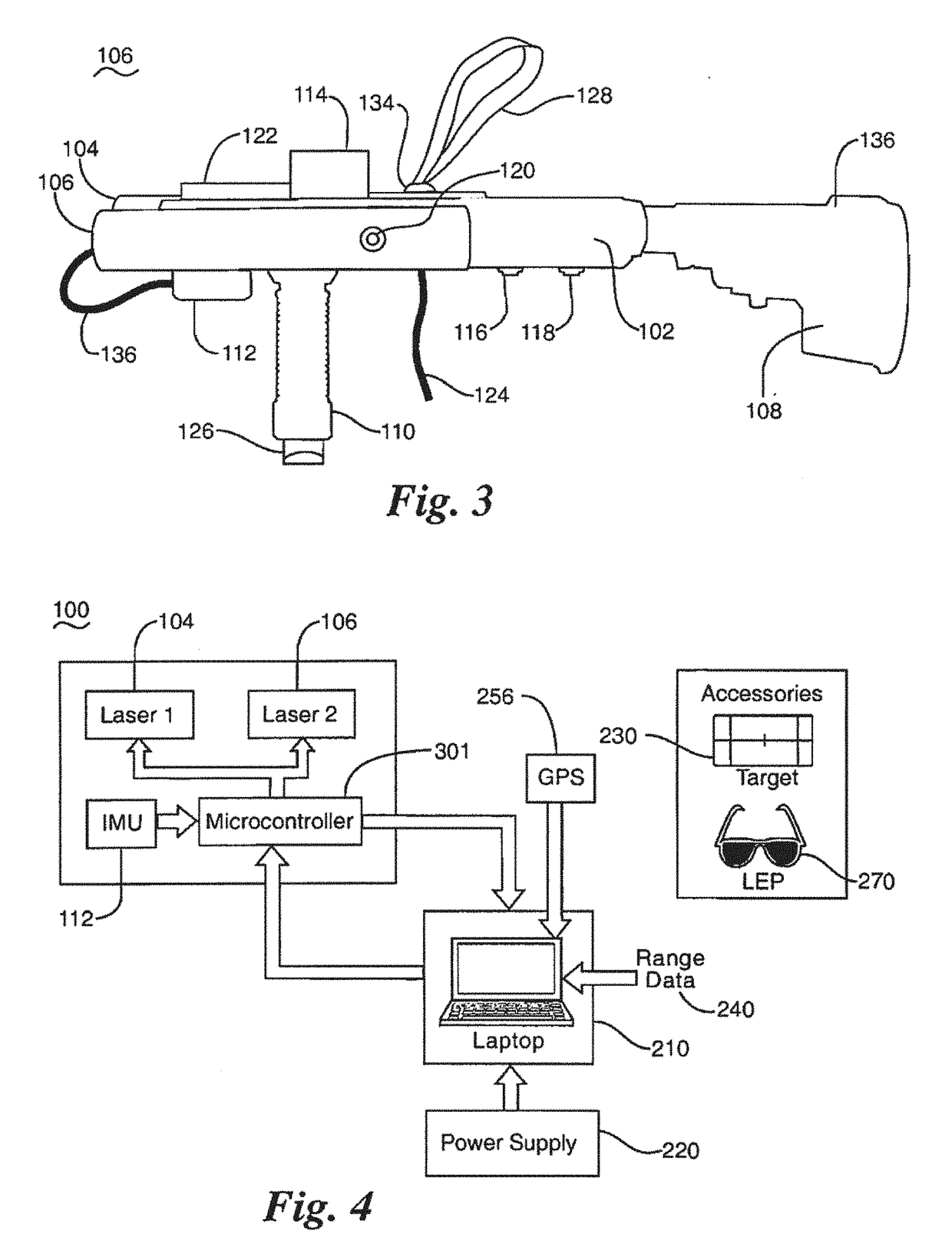
[0004]The disclosed laser sensor stimulator provides a low-cost, agile means to support the development, testing, and periodic validation of ground and airborne laser sensors. It also can be used in environments where it may be advantageous to stimulate airborne laser sensors during flight operations. The laser sensor stimulator can illuminate sensors with multiple co-aligned lasers in a field environment through its ability to track aircraft and receive tracking data pertaining to aircraft and items of interest to be tracked (e.g. from a flight test range). The laser sensor stimulator monitors the direction (azimuth and elevation) in which laser energy is propagated with respect to a fixed frame of reference. The laser sensor stimulator also provides the exact spatial location of an operator. The laser sensor stimulator tracks all three components (aircraft position, laser sensor stimulator pointing direction, and laser sensor stimulator position) in real-time and provides this information to an operator in real-time via a novel user interface. For the system to be operated safely for operators, aircrews, and other personnel, certain system characteristics such as laser power levels must meet local and federal safety regulations. The laser sensor stimulator includes features that mitigate these risks such as safety lockouts based on laser safety parameters, laser keys, protective equipment, and software monitoring in addition to procedural safety measures such as training. The laser sensor stimulator records operational data concerning its activities and activities of aircraft and other items of interest it tracks and synchronizes this data to a common time code so the effectiveness of laser sensors, laser warning devices, and other devices that are stimulated by the laser sensor stimulator can be assessed.

Problems solved by technology

Traditionally, these sensors undergo extensive laboratory and ground characterization and test, but very little validation and direct-illumination during actual flight.
Existing means of in-flight characterization generally rely upon non-purpose-built, expensive, and cumbersome aircraft trackers with custom integrated and calibrated laser sources and telescopes—all requiring extensive teams of specialized engineers and technicians to employ.
These national-level test assets are in great demand and are rarely accessible to support small-scale and quick-reaction airborne laser sensor stimulation for development and test.
Moreover, their cost limits their use for small-scale development and test activities.

Method used


Image

  • Laser Sensor Stimulator
  • Laser Sensor Stimulator
  • Laser Sensor Stimulator

Examples


Embodiment Construction

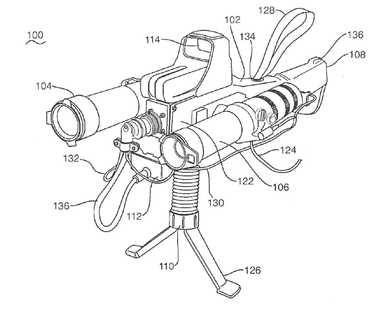
[0018]As disclosed herein, a laser sensor stimulator 100 includes a housing 102, laser units 104, 106, a rifle stock 108, a tactical foregrip 110, an inertial measurement unit 112, a sight 114, laser switches 116, 118, auxiliary switches 120, and a control unit 122. An umbilical cable 124 connects the laser sensor stimulator 100 to a laser sensor stimulator system described below. The housing 102 is a generally longitudinal shell that provides a platform for mounting the other components of the stimulator 100. The laser units 104, 106 are attached to the housing 102 with one laser unit 104, 106 positioned on each side of the housing 102 with the longitudinal axis of each laser unit 104, 106 aligned with the longitudinal axis of the housing 102. The laser units 104, 106 are connected to the housing 102 via quick-release mounts (not shown) to permit rapid assembly and disassembly of the stimulator 100 and easy exchange of different laser units. The laser units 104, 106 may be any port...


PUM


Abstract

A laser sensor stimulator integrates laser units, an inertial measurement unit, a control unit, and ergonomic, modular design with GPS data feeds into a portable system that can be used to test energy sensors and warning devices and includes a user interface facilitates tracking and acquisition of items of interest by the laser sensor stimulator.

Description

CROSS-REFERENCE TO RELATED APPLICATIONS[0001]This application is a divisional of U.S. application Ser. No. 13 / 103,440, entitled “Laser Sensor Stimulator,” filed on May 9, 2011, the entirety of which is incorporated by reference herein.RIGHTS OF THE GOVERNMENT[0002]The invention described herein may be manufactured and used by or for the Government of the United States for all governmental purposes without the payment of any royalty.BACKGROUND OF THE INVENTION[0003]Several classes of laser detection, characterization, and warning receivers have been developed for employment on civilian and military aircraft. Traditionally, these sensors undergo extensive laboratory and ground characterization and test, but very little validation and direct-illumination during actual flight. Existing means of in-flight characterization generally rely upon non-purpose-built, expensive, and cumbersome aircraft trackers with custom integrated and calibrated laser sources and telescopes—all requiring exte...

Claims


Application Information

Patent Timeline
Patent Type & Authority Applications(United States)
IPC IPC(8): H05B37/00G01B21/00F41G1/32F41G1/00F21V33/00G01C3/08F21V21/00
CPCF21V33/00F21V21/00G01B21/00H05B37/00F41G1/00F41G1/32G01C3/08F41C23/00F41G1/54F41G3/145F41H11/02G01S7/4804
Inventor CAIN, ANTHONY M.HUGH, DANNY J.THOMAS, DONALD R.DAVIDSON, SHAWN R.
Owner THE UNITED STATES OF AMERICA AS REPRESETNED BY THE SEC OF THE AIR FORCE
Why Eureka
Eureka Blog
Learn More