
3D Color Mapping and Tuning in an Image Processing Pipeline

a pipeline and image processing technology, applied in the field of digital image and video processing, can solve problems such as less than desirable smoothness for various hues

Active Publication Date: 2017-12-14
GOPRO
View PDF0 Cites 11 Cited by
  • Summary
  • Abstract
  • Description
  • Claims
  • Application Information

AI Technical Summary

Benefits of technology

The patent text discusses the importance of color and tone mapping in the capture and reproduction of images. The technical problem addressed is how to optimize color and tone mapping to minimize undesirable artifacts and improve image quality. The patent describes several embodiments and methods for achieving this goal, including the use of 2D look-up tables and transform coefficients. The patent also mentions the use of dynamic global tone mapping and the integration of dynamic global tone mapping into a 3D color LUT. Overall, the patent aims to provide a solution for improving the quality of captured images and the overall visual experience of the audience.

Problems solved by technology

The adjustment to the chroma and hue can result in a less than desirable smoothness for various hues with varying chroma.
In addition to color mapping, tone mapping can play an important role in the capture, storage and reproduction of images because often the bit depth of the image's pixels has a limited dynamic range that is inadequate to capture all of the light intensities present in real-life scenes.
However, when a scene contains both shadowed and bright features, application of a single tone map may compress features on either edge of the spectrum due to the limited bit depth of the tone map.

Method used


Image

  • 3D Color Mapping and Tuning in an Image Processing Pipeline
  • 3D Color Mapping and Tuning in an Image Processing Pipeline
  • 3D Color Mapping and Tuning in an Image Processing Pipeline

Examples


example camera

Configuration

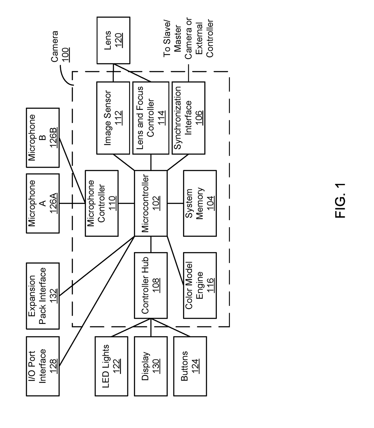
[0020]FIG. 1 illustrates an example high-level block diagram of a camera system 100 for implementing color mapping and tone mapping within a digital image, according to one embodiment. The camera 100 of the embodiment of FIG. 1 includes one or more microcontrollers 102, a system memory 104, a synchronization interface 106, a controller hub 108, one or more microphone controllers 110, an image sensor 112, a lens and focus controller 114, a color and tone mapping engine 116, one or more lenses 120, one or more LED lights 122, one or more buttons 124, one or more microphones 126, an I / O port interface 128, a display 130, and an expansion pack interface 132.

[0021]The camera 100 includes one or more microcontrollers 102 (such as a processor) that control the operation and functionality of the camera 100. For instance, the microcontrollers 102 can execute computer instructions stored on the memory 104 to perform the functionality described herein. It should be noted that alth...

example color

Space

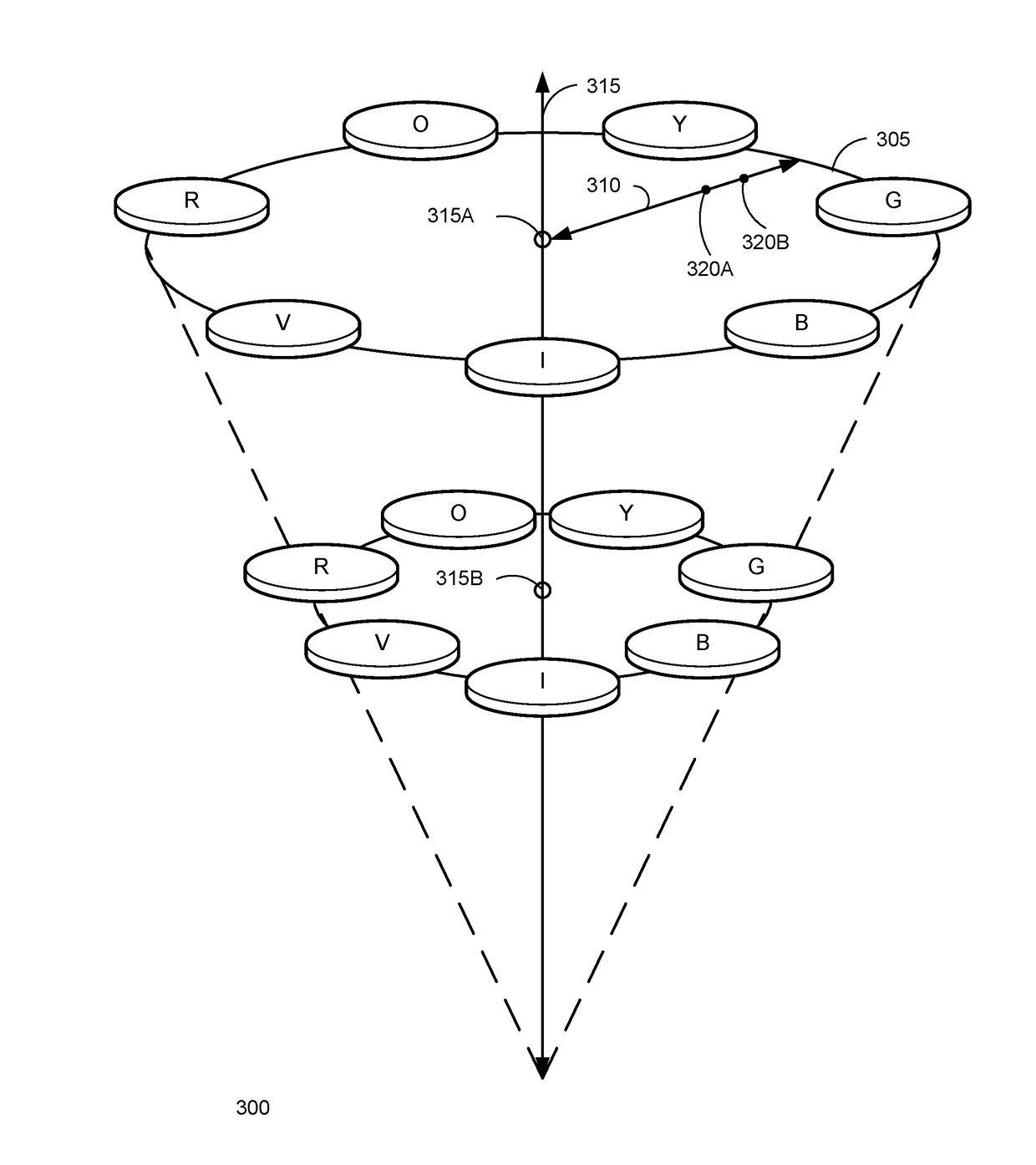
[0047]FIG. 3A illustrates an example color space 300 based on chroma, hue, and lightness, according to one embodiment. A chroma, hue, and lightness color space is illustrated for the purposes of discussion, but it should be noted that any other suitable color space can be used with the processes described herein. Chroma 310 represents saturation, hue 305 represents color, and lightness 315 represents the lightness of the chroma 310 and hue 305. For varying lightness measures 315A and 315B, various points 320A and 320B representing chroma are determined for corresponding hue levels 305. As shown in FIG. 3A, various lightness in the color space 300 are represented on various z-axis planes of the color space 300, also shown in FIG. 3B. Adjusting a chroma measure from 320A to 320B can be difficult depending on a corresponding hue measure. For example, adjusting chroma 310 for a red hue 305 varies saturation of red more noticeably than adjusting chroma 310 for a green hue 305.

[0048]...


PUM


Abstract

The processing of RGB image data can be optimized by performing optimization operations on the image data when it is converted into the YCbCr color space. First, a raw RGB color space is converted into a YCbCr color space, and raw RGB image data is converted into YCbCr image data using the YCbCr color space. For each Y-layer of the YCbCr image data, a 2D LUT is generated. The YCbCr image data is converted into optimized CbCr image data using the 2D LUTs, and optimized YCbCr image data is generated by blending CbCr image data corresponding to multiple Y-layers. The optimized YCbCr image data is converted into sRGB image data, and a tone curve is applied to the sRGB image data to produce optimized sRGB image data.

Description

BACKGROUNDField of Art[0001]The disclosure generally relates to the field of digital image and video processing, and more particularly to the implementation of color mapping and tone mapping within a camera architecture.Description of the Related Art[0002]Digital cameras capture images using an electronic image sensor. Example image sensors use CCD (charge-coupled device) or CMOS (complementary metal-oxide semiconductor) technology. For example, a CMOS image sensor contains photodiodes corresponding to pixels of a captured image. The captured image is presented in a RAW color space associated with the CMOS image sensor. The chroma, hue, and lightness of the captured image can be adjusted using color mapping after the image is captured by the camera. Color mapping maps the RAW color space to a target color space in order to achieve an accurate or preferred color reproduction for captured images. The adjustment to the chroma and hue can result in a less than desirable smoothness for v...

Claims


Application Information

Patent Timeline
IPC IPC(8): H04N1/60G06T1/20
CPCH04N1/6019G06T1/20H04N1/6008H04N1/6005H04N1/6027H04N23/86H04N23/85H04N9/67H04N9/68
Inventor CHEN, YINGCHAWLA, SUMITEDWARDS, ELIZABETH TORRESCHANDU, KARTHEEKDING, BO
Owner GOPRO
Learn More