
Assembly system for modular industrial plants

a technology for industrial plants and assembly systems, applied in industrial buildings, building components, shock-proofing, etc., can solve problems such as inability to directly propagate, and achieve the effect of strengthening the overall facility

Active Publication Date: 2017-12-07
RV LIZENZ
View PDF16 Cites 8 Cited by
  • Summary
  • Abstract
  • Description
  • Claims
  • Application Information

AI Technical Summary

Benefits of technology

The invention is a modular facility that allows for easy planning and design, as well as efficient assembly and disassembly. The facility is also secure against extreme mechanical stresses such as earthquakes or storms, and can withstand general weather effects. Connecting modules at their side faces can also be beneficial.

Problems solved by technology

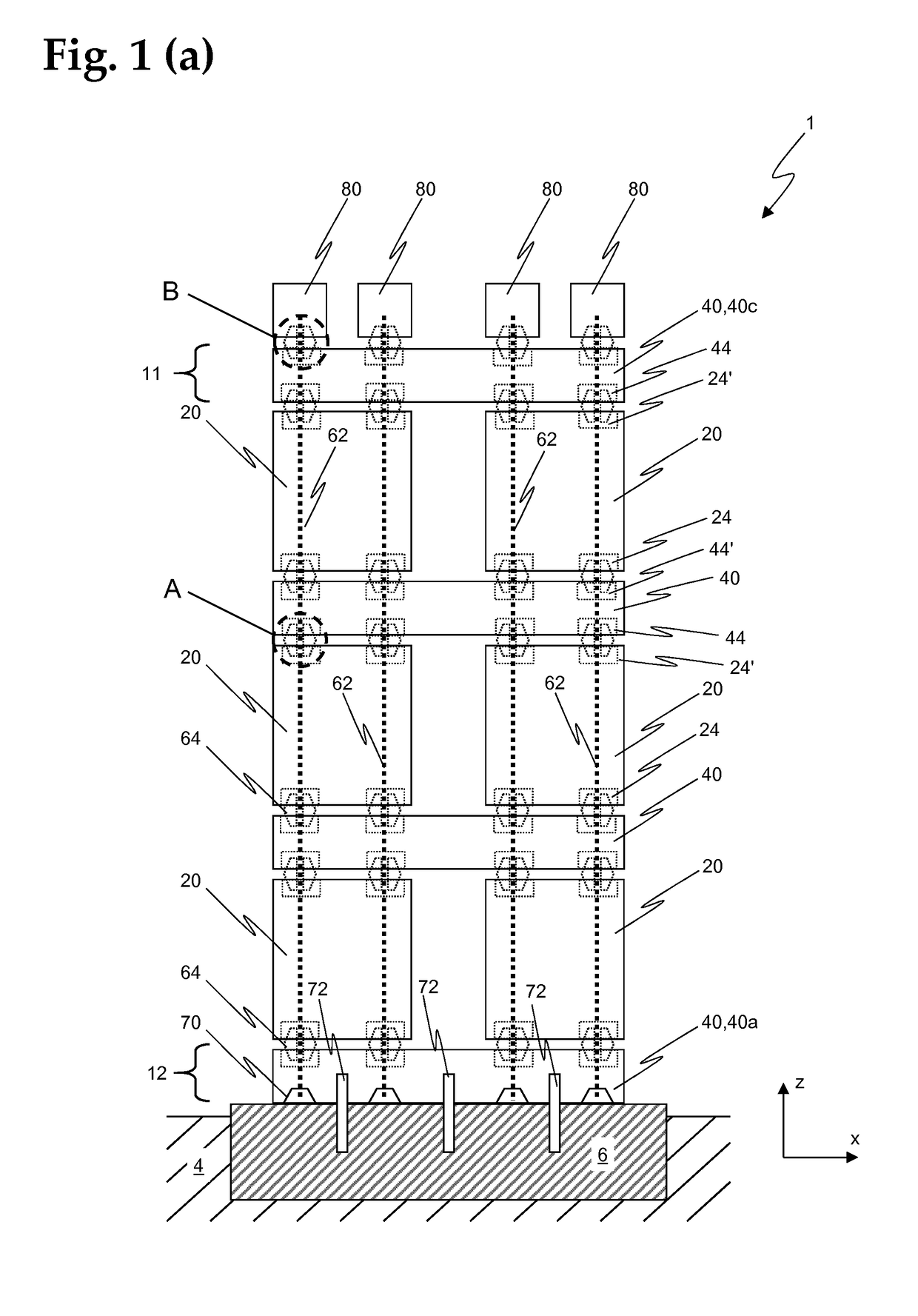
The interlocked stacking of the modules has the effect that forces acting on individual modules, for example due to wind, earthquakes, or mechanical vibrations from machines and devices running in the facility, are not able to directly propagate through the facility structure, and instead are deflected in different directions of the structure.

Method used


Image

  • Assembly system for modular industrial plants
  • Assembly system for modular industrial plants
  • Assembly system for modular industrial plants

Examples


Embodiment Construction

[0025]Within the scope of the present disclosure, the term “modular facility” refers, among other things, to industrial facilities made up of individual modules, for example chemical production facilities in which various components (for example, reactors, tanks, filters, pumps, heat exchangers, etc.) are typically in operative connection with one another, for example via lines, etc.

[0026]Such industrial facilities may also include other processing facilities, for example devices for crushing, washing, sorting, or transporting rock, for example in mining. Power plants may also have a modular construction. For example, a facility for utilizing carbon-containing materials and for generating energy is known from WO 2011 / 061299 A1 by the present applicant. Such a facility may also be implemented as a modular facility.

[0027]It is clear to those skilled in the art that the term “modular facility” encompasses essentially all technical or industrial facilities and units that are or may be m...


PUM


Abstract

The invention relates to a modular plant (1), in particular a modular industrial plant, comprising a plurality of cuboid-shaped plant modules (20, 40, 40a, 40c), which are arranged in two or more layers stacked one above the other. The modules have a support structure having fastening points (24, 24′, 44, 44′), wherein the fastening points are provided for connecting a module to corresponding fastening points of the adjacent modules of a layer located above and / or below thereof. In the horizontal plane, the modules of a layer are connected to the adjacent modules of the layer located above and / or below thereof in a form-fit manner by means of a connection element (64) having the shape of a double cone or of a double conical frustum. At least one traction device (62, 70, 80) having a tension member (62) is provided, by way of which traction device a bottom layer of modules (40a) or a foundation block (6) can be impinged upon with a tensile force along the vertical, with respect to a top layer of modules (40c) such that along the vertical, the modules between said bottom layer (12) and said top layer (11) and the adjacent modules of the layer located above and / or below thereof are positively pressed together at the fastening points and are thus fixed in place.

Description

FIELD OF TECHNOLOGY[0001]The invention relates to modular facilities, in particular modular industrial facilities, supply facilities, production facilities etc. The invention further relates to modules for such facilities, and assembly sets for constructing modular facilities, according to the preambles of the independent claims.TECHNOLOGICAL BACKGROUND[0002]For certain facilities, in particular industrial facilities, supply facilities, production facilities, etc., it may be desirable to construct them in a modular manner, for example to allow rapid and efficient adaptation to new requirements. This may be the case for chemical production facilities, for example, when a change in the product to be produced makes it necessary to adapt or exchange the individual components. Such large chemical facilities frequently require the arrangement of a fairly large number of facility modules in multiple assembly levels situated one above the other. For this purpose, several types of open frame...

Claims


Application Information

Patent Timeline
Patent Type & Authority Applications(United States)
IPC IPC(8): E04H5/02E04H9/02E04B1/98E04B1/348F16F15/04E04B1/343E04B1/35E04B1/41E04C3/34
CPCE04H5/02E04H9/021E04B1/3483E04B1/98E04B2001/3583E04B1/34352E04B1/4157E04C3/34E04B1/34321F16F15/04
Inventor RUDLINGER, MIKAEL
Owner RV LIZENZ
Learn More