
Furniture base assembled from several parts

Inactive Publication Date: 2017-11-30
AF SOLUTIONS AB OY
View PDF22 Cites 3 Cited by
  • Summary
  • Abstract
  • Description
  • Claims
  • Application Information

AI Technical Summary

Benefits of technology

[0008]The object of the present invention is to provide a furniture base which allows varying its height. This is accomplished by changing the angle between hub and arms, or by shifting the points of attachment of the arms on the hub in the vertical direction.
[0009]The furniture base according to the present invention i

Problems solved by technology

Such a furniture base, however, requires a disproportional amount of space during transport.
During manufacturing, fairly bul

Method used


Image

  • Furniture base assembled from several parts
  • Furniture base assembled from several parts
  • Furniture base assembled from several parts

Examples


Example

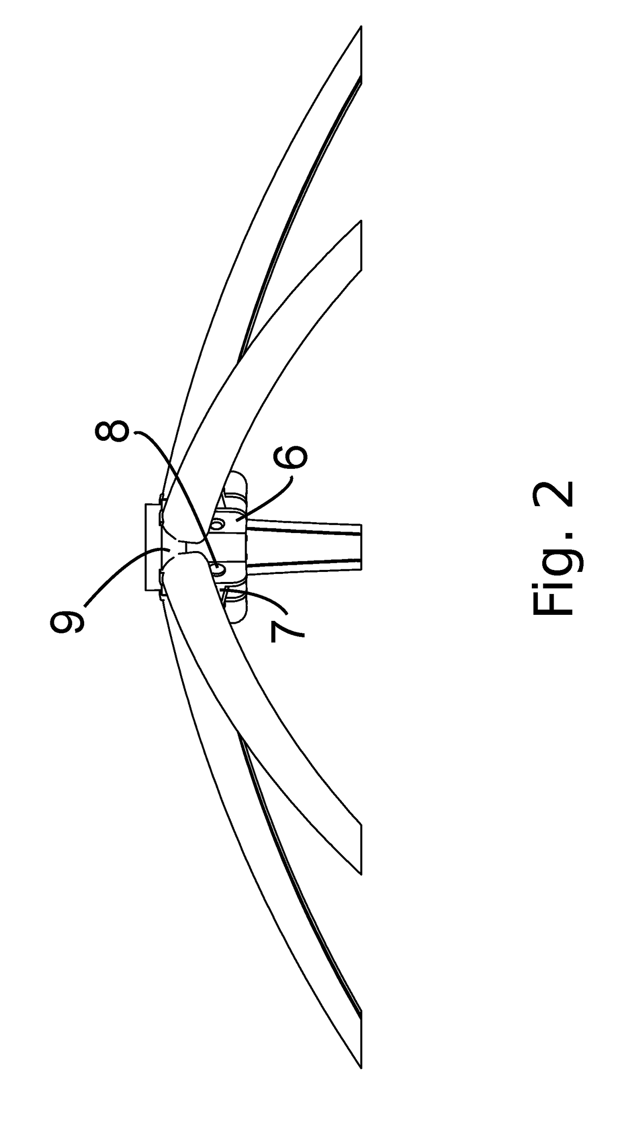
[0035]In the figures, all equivalent parts have not been provided with reference numerals when the objects are symmetrical.

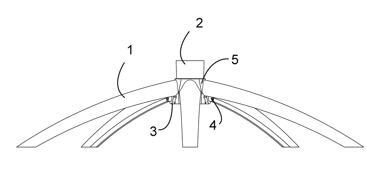
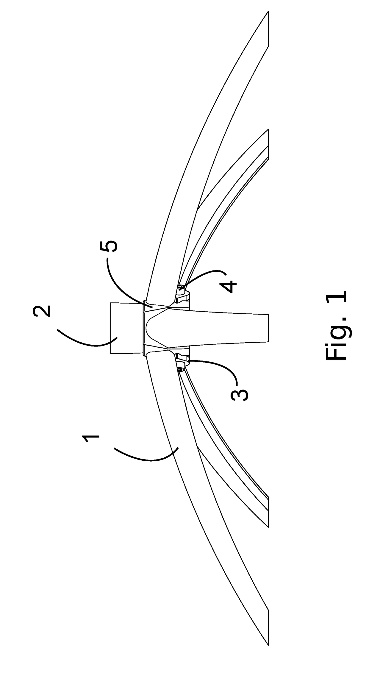
[0036]In FIG. 1 is depicted a side view of a furniture base according to the invention. The arms 1 are manufactured from steel sheet, whereby blanks have been cut from planar material and initially bent to a U-profile, providing the necessary stiffness, after which a further bending has been carried out to achieve an esthetical curvature. In the figures, this curvature is upward concave throughout, but it may also be the opposite. In the arms are provided end flanges 3 with holes for radially directed screws 4. The holes are located close to the lower edge of the flange, and the upper edge of the proximal end of the arm abuts the hub 2. Here, the hub is cylindrical, i.e. has a circular section. To match the contact area between the planar end flange 3 and the curved surface on the hub 2, a spacer body 5 has been fitted between the surfaces, preferably so that th...


PUM


Abstract

The invention is directed to a base for pieces of furniture having at least one supporting column structure. The base comprises a central hub receiving the lower end of a column and a number of arms radiating from the hub. The object of the invention is to provide a furniture base which allows varying its height. This is accomplished by changing the angle between hub and arms, or by shifting the points of attachment of the arms on the hub in the vertical direction.

Description

[0001]The invention is directed to a base for pieces of furniture having at least one supporting column structure. More specifically, the invention is directed to a base assembled from a plurality of parts, comprising a hub and arms radiating therefrom.BACKGROUND[0002]Chairs having a central column are popular in particular as office chairs, but also for private use when a there is a need for a chair which is rotatable while stationary. Such chairs may be provided with various mechanisms for rotation, tilting, gas or spring suspension in the column, among others. A prerequisite for such a chair is a robust base structure, with or without wheels for moving around.[0003]Also tables may be provided with one or more columns, for example along a central line, whereby the legs are not in the way of persons seated around the table. A centrally located column is not required e.g. on desk-type furniture.[0004]For furniture which is to be stationary, a flat base plate may be employed. In part...

Claims


Application Information

Patent Timeline
IPC IPC(8): F16M11/24A47B9/16A47C3/36A47C7/00A47B13/02
CPCF16M11/242A47C7/004A47B13/023A47C3/36A47B2013/025F16M2200/08F16M2200/068F16M2200/065A47B9/16A47B2013/024A47B91/005A47B13/02A47B91/00A47C3/18
Inventor KJELLMAN, FREDRIK
Owner AF SOLUTIONS AB OY
Learn More