
Height adjustable stand and a table comprising the same

a technology of adjustable stands and tables, applied in the direction of stands/trestles, variable height tables, rod connections, etc., can solve the problems of inconvenient and time-consuming process, inability to adjust the height of adjustable stands known in the art, and inability to adjust the height of adjustable stands on an uneven surface. , to achieve the effect of improving the reliability of the adjustable stand, saving a lot of time, and increasing user comfor

Inactive Publication Date: 2017-11-16
SMART LEVEL TABLE BV
View PDF0 Cites 2 Cited by
  • Summary
  • Abstract
  • Description
  • Claims
  • Application Information

AI Technical Summary

Benefits of technology

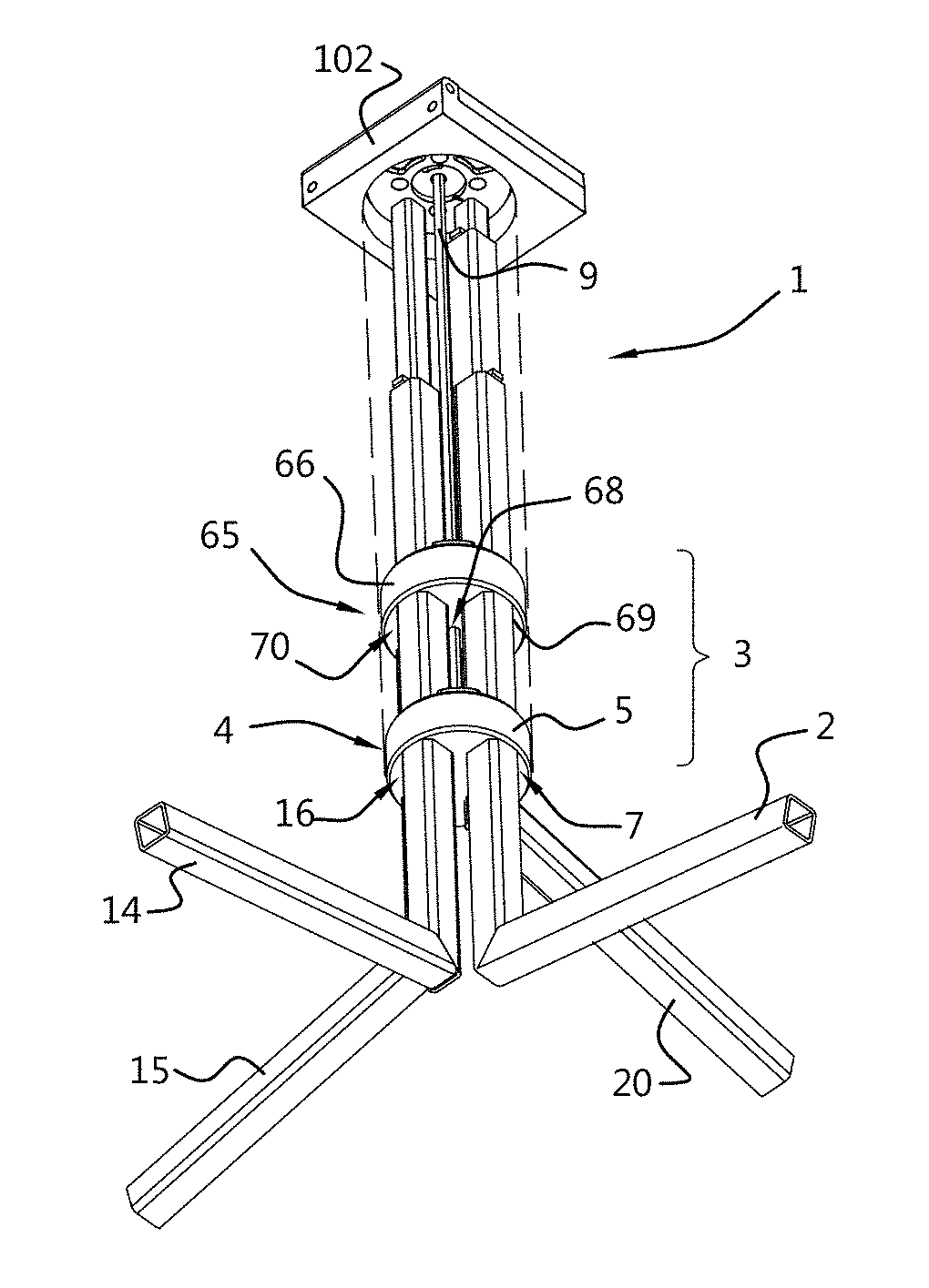
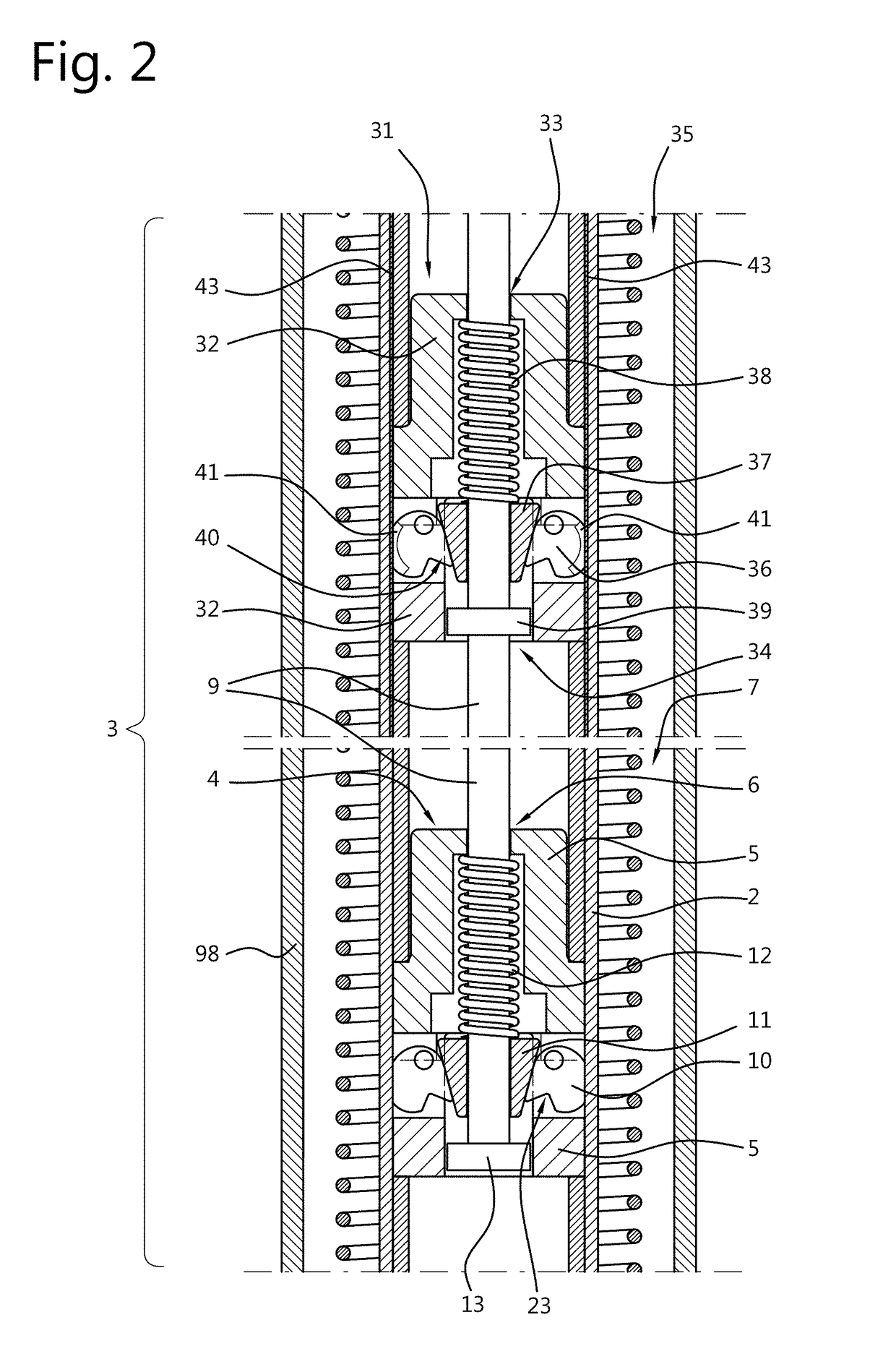
The invention is about a stand for supporting an object with a locking device that allows for easy adjustment of the height of the stand. The stand includes a first leg and a first locking device with a housing and a guideway for receiving the first leg. The stand also has a central operating device for adjusting the height of the stand. The locking device includes a locking element, an activation element, and a biasing element. The stand can be connected to a table leaf, which allows for easy adjustability and stability on uneven surfaces. The technical effects of this invention include a stand that is easy to use, secure, and stable, as well as a table with a height adjustable stand that saves time.

Problems solved by technology

Adjusting the height of stands known in the art usually can be quite cumbersome as it involves a series of operations that a user needs to employ due to the construction of the locking devices used.
Moreover, in the case of stands known in the art having multiple legs, leveling of these stands on an uneven surface is usually even more cumbersome as a length of the legs has to be adjusted individually requiring an iterative process to establish suitable lengths for each of the individual legs.
Such a process can be inconvenient and time consuming as for example the stand needs to be supported by a user while the lengths of each of the individual legs are adjusted.

Method used


Image

  • Height adjustable stand and a table comprising the same
  • Height adjustable stand and a table comprising the same
  • Height adjustable stand and a table comprising the same

Examples


Embodiment Construction

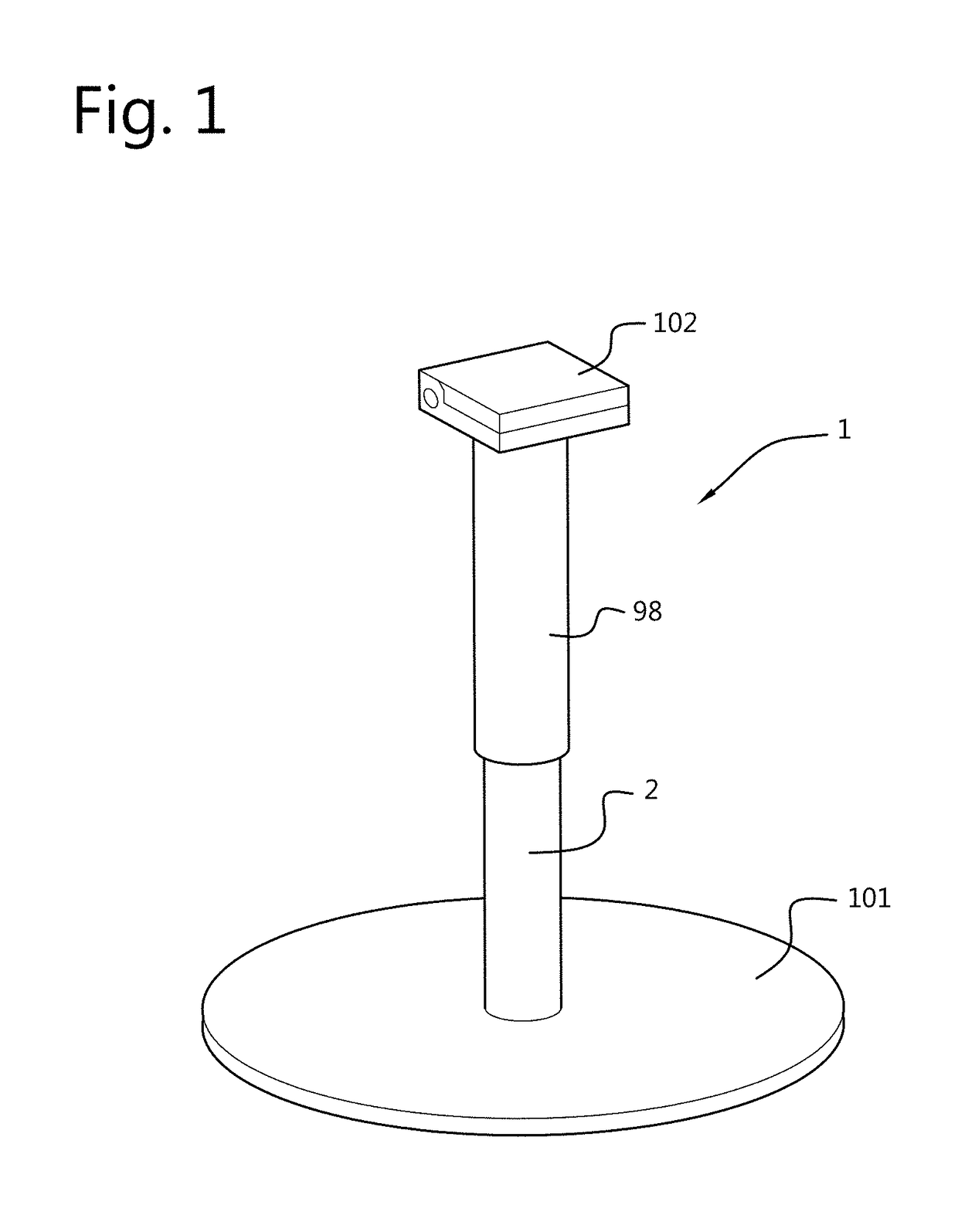
[0092]FIG. 1 shows a perspective view of an exemplary embodiment of a height adjustable stand 1 according to the invention comprising a first leg 2. At a first end of the leg 2 a footplate 101 is provided that is arranged, in use of the stand 1, to position the stand 1 stably on a supporting surface. At an opposing second end of the leg 2 a coupling arrangement 102 is provided that is connectable with an object to be supported, e.g. a table leaf or a camera.

[0093]The stand 1 shown in FIG. 1 further comprises a first elongated tubular element 98 that is arranged coaxially with the first leg to at least partially envelop the first leg 2. In this way, the first leg 2 can at least partially be protected from the outside environment in which the stand 1 is placed. As a result, the reliability of the stand 1 can be improved. Furthermore, the first elongated tubular element 98 allows to provide the stand 1 with any desired appearance, e.g. colour, design pattern, etcetera. In the following...


PUM


Abstract

Disclosed is a height adjustable stand for supporting an object, such as a table leaf or a camera. The invention also relates to a table including the stand. The stand includes at least a first leg, at least a first locking device and at least a first central operating device including at least a first elongated operating element that is arranged to allow the first locking device to be transferred from a locked resting state to an unlocked state in which the height of the stand is adjustable. The construction of the stand is lean and robust allowing height adjustment and stable positioning of the stand and thereby the table, even on uneven supporting surfaces simultaneously. User comfort is improved as precious time can be saved especially when installing multiple stands or tables.

Description

FIELD OF THE INVENTION[0001]The invention relates to a height adjustable stand for supporting an object, such as a table leaf or a camera. The invention also relates to a table comprising said stand. The height adjustable stand in the context of this invention is neither intended nor suitable for supporting at least one person or very heavy loads.BACKGROUND OF THE INVENTION[0002]Adjusting the height of stands known in the art usually can be quite cumbersome as it involves a series of operations that a user needs to employ due to the construction of the locking devices used. As a result, setting up and adjusting the heights of multiple stands known in the art is quite time consuming and is preferably avoided as much as possible. Moreover, in the case of stands known in the art having multiple legs, leveling of these stands on an uneven surface is usually even more cumbersome as a length of the legs has to be adjusted individually requiring an iterative process to establish suitable l...

Claims


Application Information

Patent Timeline
IPC IPC(8): A47B9/20A47B9/06A47B9/12F16M11/32
CPCA47B9/20A47B9/06A47B9/12F16M11/32A47B2009/065A47B2200/0051A47B9/02A47B9/083F16B7/1463A47B2200/0022
Inventor BUS, KAROLUSTHEODORUS WILHELMINA MARIA
Owner SMART LEVEL TABLE BV
Learn More