
Autonomous mower navigation system and method

a mower and autonomous technology, applied in the field of navigation, can solve the problems of complex navigation system, large computational capacity and relatively expensive hardware, and methods are prone to interference from other transmitters

Active Publication Date: 2017-11-09
MTD PRODUCTS
View PDF10 Cites 15 Cited by
  • Summary
  • Abstract
  • Description
  • Claims
  • Application Information

AI Technical Summary

Benefits of technology

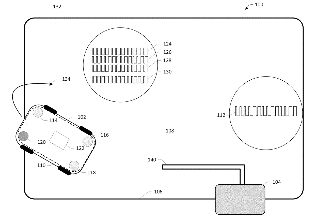
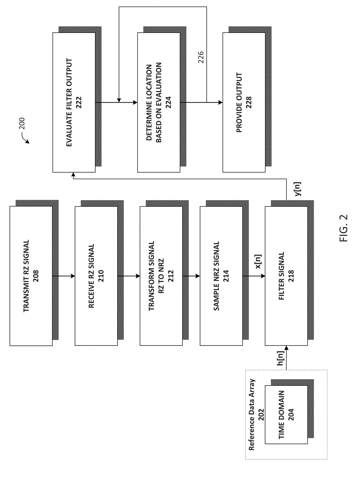
The patent describes a computer-based system for helping autonomous mowers navigate through a work area. The system uses a return-to-zero encoded signal that is transformed to a non-return-to-zero representation and then sampled in a time domain. The sampled signal is filtered using a reference data array based on the return-to-zero encoded signal to produce a filter output. This filter output is then used to determine the location of the autonomous device relative to the work area. The technical effect of this system is to provide a more accurate and reliable navigation system for autonomous mowers, which can help them navigate through complex work areas with greater precision.

Problems solved by technology

Many conventional autonomous mower navigation systems and methods, or systems and methods for confining a robot to a work area, involve complex navigation systems.
These complex and expensive systems generally require that the autonomous device be aware of its current location on a given map and can cause the autonomous device to move in a specific predetermined path.
Such methods often include Global Positioning System (GPS) technology and can require significant computational capacity and relatively expensive hardware.
These methods are prone to interference from other transmitters, for example, other autonomous device wires, dog fences, and the like.
Conventional efforts to reduce the effects of interference have included the use of modulated codes and relatively complex signals, however, these signals require additional computing power to process.

Method used


Image

  • Autonomous mower navigation system and method
  • Autonomous mower navigation system and method
  • Autonomous mower navigation system and method

Examples


Embodiment Construction

[0028]The following terms are used throughout the description, the definitions of which are provided herein to assist in understanding various aspects of the subject disclosure.

[0029]As used herein, the term “autonomous mower” refers to an autonomous robot, or most any autonomous device or machine that performs various tasks and functions including lawn mowing, lawn maintenance, vacuum cleaning, floor sweeping and the like.

[0030]As used herein, the term “navigation” refers to confinement, or confining an autonomous mower to a work area, determining a location of a robotic mower in relation to a work area, boundary sensing, localization, directing movement of an autonomous mower, ascertaining a position of an autonomous mower, and / or planning and following a route.

[0031]As used herein, the term “wire” refers to a wire loop, perimeter wire, perimeter wire loop, conductor, boundary wire, boundary conductor, or other boundary marker for defining a work area. The term “wire” can also ref...


PUM


Abstract

A method for autonomous mower navigation includes receiving a return-to-zero encoded signal including a pseudo-random sequence, transforming the received signal to a non-return-to-zero representation, digitally sampling the non-return-to-zero signal representation in a time domain, filtering the sampled signal utilizing a reference data array based on the return-to-zero encoded signal to produce a filter output, and determining a location of the autonomous mower relative to a defined work area based on an evaluation of the filter output.

Description

CROSS REFERENCE TO RELATED APPLICATIONS[0001]This application claims the benefit of U.S. Provisional Application No. 62 / 332,534, filed May 6, 2016, the entire disclosure of which is hereby incorporated herein by reference.FIELD OF THE INVENTION[0002]The disclosed systems and methods are directed to navigation, and more particularly, autonomous mower navigation systems and methods. In an aspect, the disclosed systems and methods are suitable for determining a location of an autonomous mower in relation to a work area, confining or localizing an autonomous mower to a work area, and directing movement of the autonomous mower.BACKGROUND OF THE INVENTION[0003]Many conventional autonomous mower navigation systems and methods, or systems and methods for confining a robot to a work area, involve complex navigation systems. These complex and expensive systems generally require that the autonomous device be aware of its current location on a given map and can cause the autonomous device to mo...

Claims


Application Information

Patent Timeline
Patent Type & Authority Applications(United States)
IPC IPC(8): G05D1/02A01D34/00H03M13/15A01D101/00
CPCG05D1/0276G05D1/0265A01D2101/00H03M13/156G05D2201/0208A01D34/008G01S2205/01G01S5/0205
Inventor CHURAVY, CHRISTOPHER J.BLANCHARD, EDWARD J.
Owner MTD PRODUCTS
Learn More