
Perforating cap, particularly for a flexible tube

a flexible tube and perforating technology, applied in the field of flexible tubes, can solve the problem of inconvenient user number of steps

Active Publication Date: 2017-10-19
ALBEA SERVICES SAS
View PDF4 Cites 5 Cited by
  • Summary
  • Abstract
  • Description
  • Claims
  • Application Information

AI Technical Summary

Benefits of technology

The invention described in this patent allows for a tube to have a cap that can be held in a standby position without needing any additional parts. This means that the tube is always protected from any damage or cutting before being used. The use of a spacer ring, which is typically used to keep the cap's punch away from the lining of the tube, is avoided. This simplifies the closure assembly and ensures the tube remains safe and secure.

Problems solved by technology

The number of steps is inconvenient for the user, who often does not understand the purpose of the ring and also does not necessarily understand that a closure liner has to be perforated before the first use of the tube.

Method used


Image

  • Perforating cap, particularly for a flexible tube
  • Perforating cap, particularly for a flexible tube
  • Perforating cap, particularly for a flexible tube

Examples


Embodiment Construction

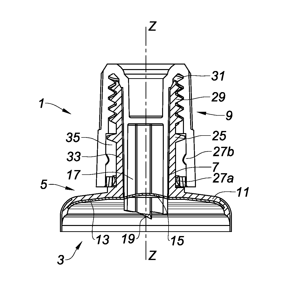
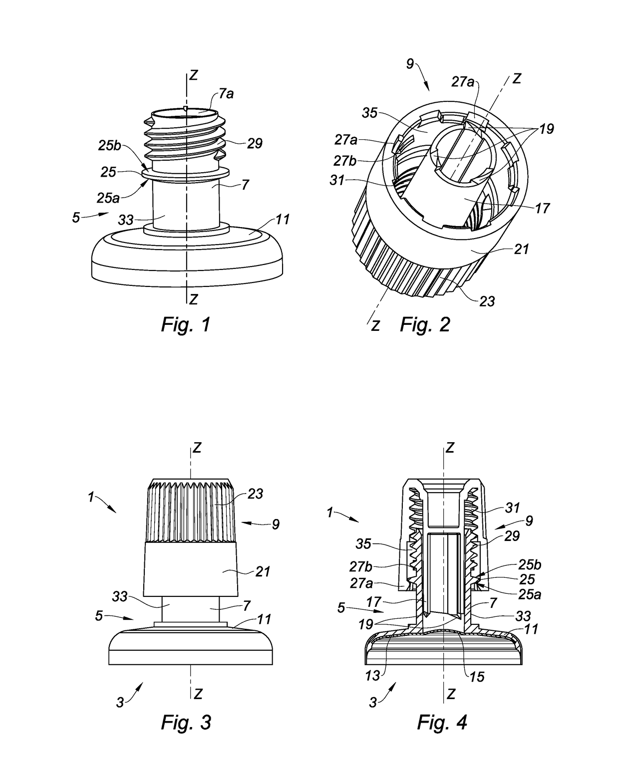
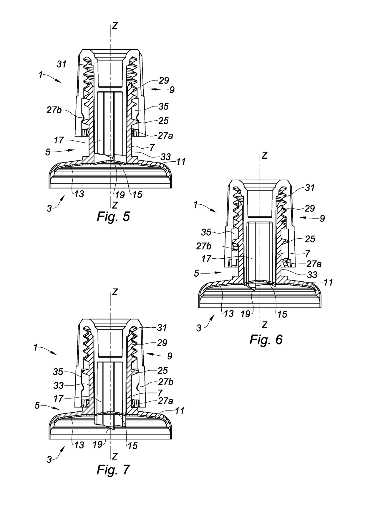
[0116]As shown in the various Fig., the invention relates to an assembly 1 for closing a tube 3. The assembly 1 includes:[0117]a tube head 5 including a neck 7; and[0118]a cap 9 configured to be fixed onto the neck 7, particularly by screwing.

[0119]The tube head 5, a variant of which is shown in FIGS. 1 and 3 to 8, includes the neck 7 defining a longitudinal axis Z-Z, a shoulder 11 and a full insert 13 forming a closure liner 15 sealing the neck 7, in the lower part thereof. As shown herein, the neck 7 and the shoulder 11 are designed as a single-piece and are integrally formed. The insert 13 is located against a lower face of the shoulder 11 that is intended to be oriented towards the inside of the tube.

[0120]The neck 7 in this case is in the form of a cylinder extending from an upper end, which is located towards the outside of the tube 3, towards a lower end, which is opposite the upper end and is directed towards the inside of the tube 3. The upper end has a discharge hole 7a al...


PUM


Abstract

The present invention relates to an assembly for closing a tube. The assembly includes a tube head including a neck and a closure liner sealing the neck. The assembly also includes a cap that includes a punch adapted to cut the closure liner. The neck and the cap are configured to allow the cap to be fixedly held on the neck in a first position—the standby position—in which the punch is held at a distance from the closure liner, and in a second position—the position of use—in which the punch perforates the closure liner.

Description

CROSS REFERENCE TO RELATED APPLICATIONS[0001]This application claims priority under 35 U.S.C. §119(a) to French Patent Application Serial Number 1653453, filed Apr. 19, 2016, French Patent Application Serial Number 1655899, filed Jun. 23, 2016, and French Patent Application Serial Number 1751860, filed Mar. 7, 2017, the entire teachings of which are incorporated herein by reference.BACKGROUND OF THE INVENTIONField of the Invention[0002]The present invention relates to the field of flexible tubes including a closure liner sealing the neck prior to the first use of the tube, and to a perforating cap adapted to perforate the closure liner.Description of the Related Art[0003]Tubes are known that are provided with a closure liner associated with a perforating cap including a punch adapted to perforate the closure liner.[0004]Indeed, the closure liner allows the product contained inside the tube to be hermetically preserved while it is stored prior to its first use, which represents a sig...

Claims


Application Information

Patent Timeline
Patent Type & Authority Applications(United States)
IPC IPC(8): B65D47/36B65D1/02B65D41/04B65D41/06
CPCB65D47/36B65D41/06B65D41/04B65D1/0246B65D51/22B65D51/222B65D41/08B65D35/44B65D51/243B65D2251/0015B65D2251/0093B65D41/02B65D51/225B65D2251/0028B65D2251/009
Inventor DEFERT, SYLVAIN
Owner ALBEA SERVICES SAS
Learn More