
Polycentric powered ankle prosthesis

Active Publication Date: 2017-10-12
REHABILITATION INST OF CHICAGO
View PDF3 Cites 7 Cited by
  • Summary
  • Abstract
  • Description
  • Claims
  • Application Information

AI Technical Summary

Benefits of technology

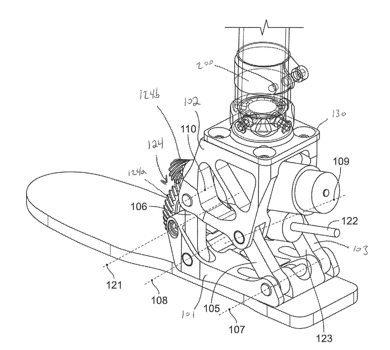
The patent describes a powered ankle prosthesis that uses a polycentric mechanism with a defined path for the center of rotation. This allows for precise and accurate movement during the stance phase of gait, improving the efficiency of the prosthesis. The prosthesis may also include an actuator to adjust the distance between the hinge of the first member and the hinge of the driven member. The polycentric mechanism fits within the contour of an anatomical foot profile, providing a natural and comfortable fit.

Problems solved by technology

However, powered ankle prostheses known in the art have drawbacks in technology and implementation.
Achieving one or more of the design goals of appropriate battery duration, structural strength, high range of motion and lightness are difficult to meet while also enclosing the design of the ankle prosthesis into an anatomical shape, such as a shape that would fit within the user's shoe.
Moreover, interchangeability and modularity (such as interfacing with the stump's socket, or pylon or torsion-elements) can be a problem due to the prosthesis dimensions and built-height, especially for transtibial amputees.

Method used


Image

  • Polycentric powered ankle prosthesis
  • Polycentric powered ankle prosthesis
  • Polycentric powered ankle prosthesis

Examples


Embodiment Construction

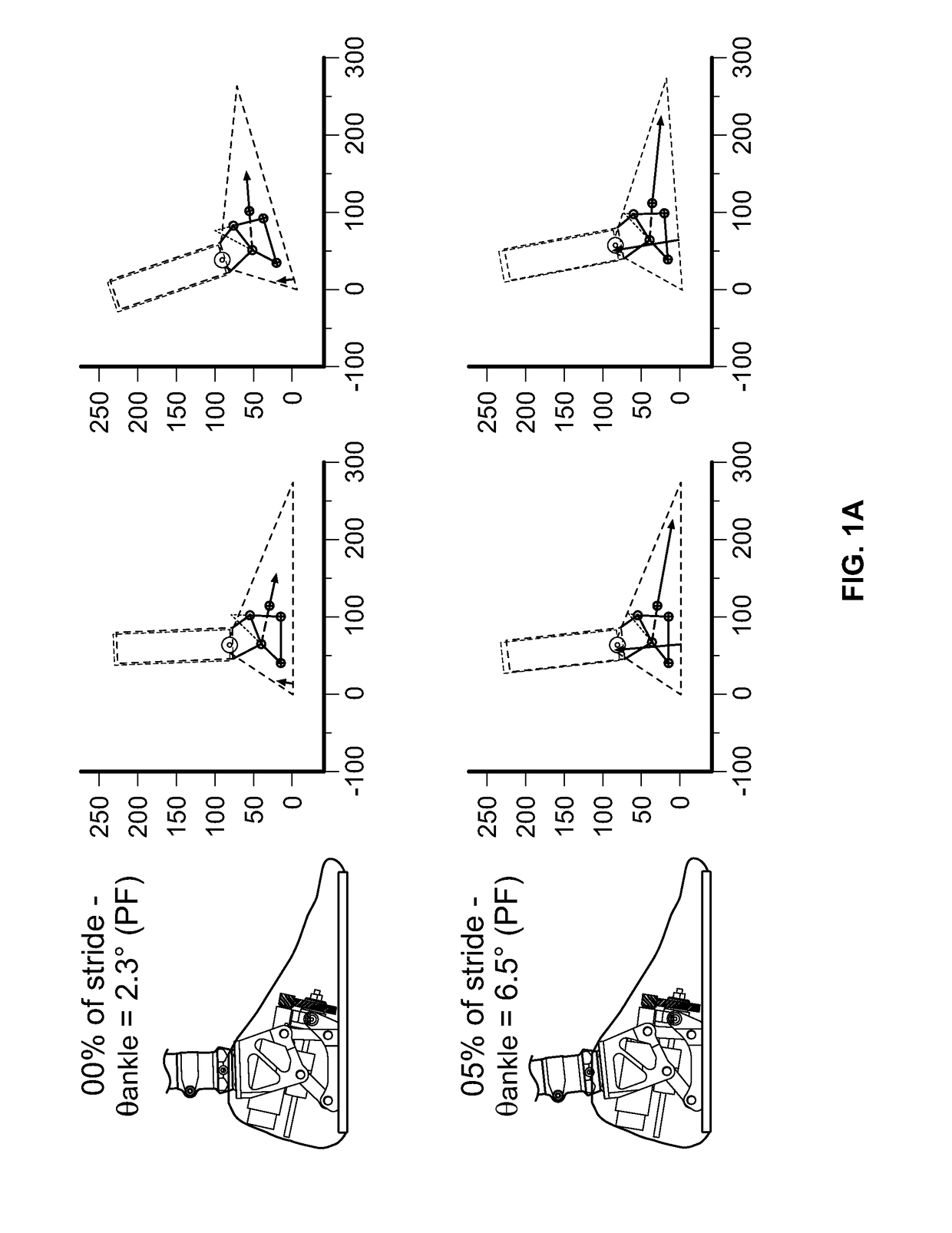
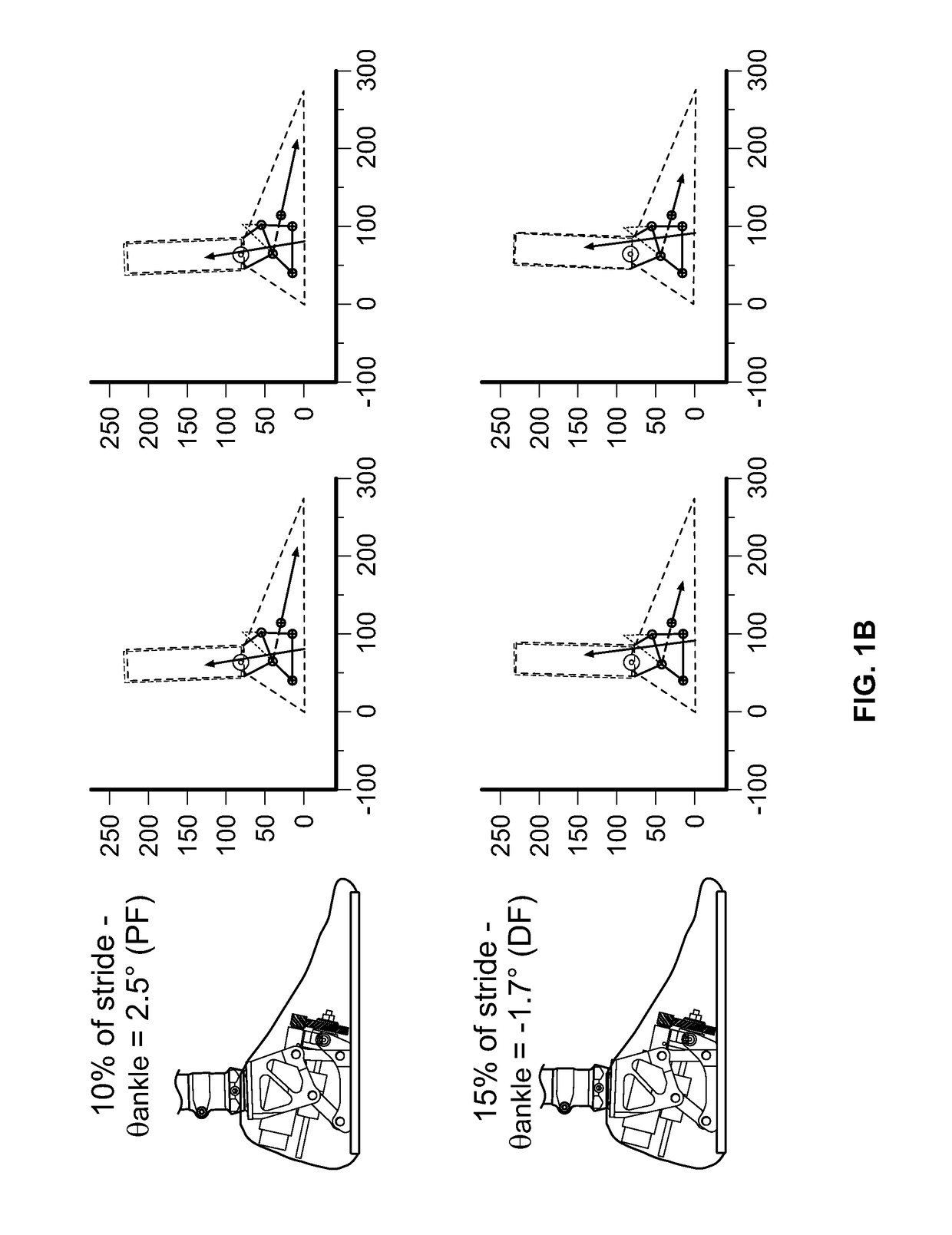
[0020]In certain embodiments, a powered ankle prosthesis is disclosed that employs a polycentric mechanism. A polycentric mechanism is one where the center of rotation of at least a portion of the mechanism changes in response to the position of at least a portion of the mechanism. The center of rotation of a polycentric mechanism is known as an “instantaneous center of rotation” or “ICR”. It is referred to as “instantaneous” because it is the center of rotation of at least a portion of the polycentric mechanism, at the particular instant at which the mechanism is at a particular position.

[0021]In an embodiment, a polycentric mechanism may comprise a first member and a second member. The first member and the send member may be connected by a joint structure. For example, the joint structure may comprise a plurality of joints that connect the first member and the second member.

[0022]Each member may comprise a one or more members to form a linkage. The polycentric mechanism may preser...


PUM


Abstract

Systems and methods are disclosed for a powered ankle prosthesis. The prosthesis may comprise a polycentric mechanism having a defined path for an instantaneous center of rotation. The path of the instantaneous center of rotation may be defined by a trajectory substantially equal to an arc positioned over a joint of the polycentric mechanism.

Description

RELATED APPLICATIONS[0001]This patent claims priority to U.S. Provisional Patent Application Ser. No. 62 / 319,430, filed on Apr. 7, 2016, entitled “Polycentric Powered Ankle Prosthesis.” The entirety of U.S. Provisional Patent Application Ser. No. 62 / 319,430 is incorporated herein by reference.CROSS REFERENCE TO RELATED APPLICATION[0002]This application is a non-provisional that claims benefit to U.S. Provisional Patent Application No. 62 / 319,430 filed on Apr. 7, 2016, which is herein incorporated by reference in its entirety.FEDERALLY SPONSORED RESEARCH OR DEVELOPMENT[0003]This invention was made with government support under Award No. 90RE5014-02-00 awarded by the National Institute on Disability, Independent Living, and Rehabilitation Research (NIDILRR), an agency of the United States Department of Health and Human Services, and under Award No. W81XWH-14-C-0105 awarded by the United States Army. The government has certain rights in the invention.BACKGROUND[0004]Prosthetic ankle de...

Claims


Application Information

Patent Timeline
IPC IPC(8): A61F2/66A61F2/70
CPCA61F2/6607A61F2/70A61F2002/7635A61F2002/6614A61F2002/701A61F2002/5038A61F2002/5021A61F2002/5027A61F2002/5018A61F2002/6836
Inventor LENZI, TOMMASOCEMPINI, MARCOKUIKEN, TODD
Owner REHABILITATION INST OF CHICAGO
Learn More