Liquid jetting apparatus
a technology of liquid jetting apparatus and protective member, which is applied in printing and other directions, can solve the problems of piezoelectric element and any thin film associated therewith being damaged, the height of the protective member may be higher than the designed size, etc., and achieve the effect of suppressing the pressing for
- Summary
- Abstract
- Description
- Claims
- Application Information
AI Technical Summary
Benefits of technology
Problems solved by technology
Method used
Image
Examples
first modified embodiment
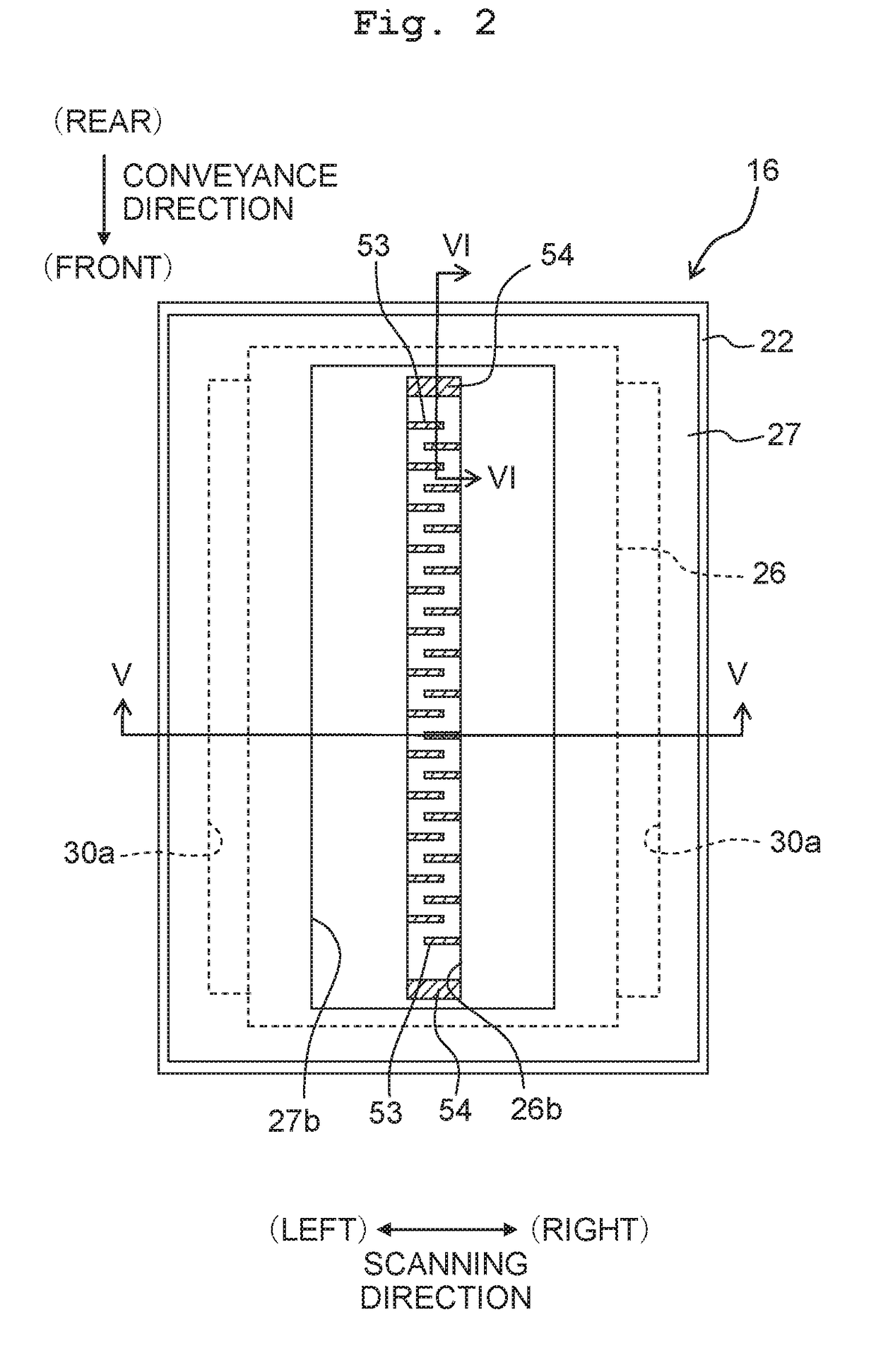
[0093]As exemplified by a head unit 16A depicted in FIG. 10, it is also allowable that the ink supply member 27 is adhered to the entire region of the upper surface of the protective member 26 disposed on the side opposite to the first flow passage member 21. When the adhesion surface between the protective member 26 and the ink supply member 27 is large, the bulging amount (rising amount), which is provided at the central portion of the adhesion surface, is increased, when the first adhesive 61 is applied to the adhesion surface. Therefore, it is easy to secure the thickness of the layer of the first adhesive 61.
second modified embodiment
[0094]The embodiment described above is illustrative of the exemplary case in which the second adhesive 62 is the adhesive sheet. However, it is also allowable that any liquid adhesive is used for both of the first adhesive 61 and the second adhesive 62. In this case, epoxy-based adhesives can be preferably used as the first adhesive 61 and the second adhesive 62 respectively. The first adhesive 61 and the second adhesive 62 may be composed of an identical material, or they may be composed of different materials.
[0095]Further, an adhesive, which has a viscosity before the curing larger than a viscosity of the second adhesive 62, may be adopted as the first adhesive 61. When the viscosity before the curing of the first adhesive 61 is high, then the first adhesive 61 hardly spreads during the adhesion, and hence it is easy to secure the thickness. For example, the viscosity of the first adhesive 61 is 100 to 200 cPs, and the viscosity of the second adhesive 62 is 10 to 100 cPs.
[0096]F...
third modified embodiment
[0097]In the embodiment described above, the flow passage member, to which the ink is supplied from the ink supply member 27, is divided into the first flow passage member 21 and the second flow passage member 22. However, there is no limitation to the embodiment as described above. In the case of a head unit 16B depicted in FIG. 11, one flow passage member 70 is formed with a plurality of pressure chambers 71 and a manifold 72. The flow passage member 70 depicted in FIG. 11 has a portion 70a which extends outwardly in the left-right direction from a portion at which the pressure chamber 71 is formed. An opening 72a of the manifold 72 is formed at the outer portion 70a. On that basis, the ink supply member 27 is adhered to the protective member 26 by means of the first adhesive 61, and the ink supply member 27 is adhered to the outer portion 70a of the flow passage member 70 by means of the second adhesive 62.
PUM
 Abstract
Description
Claims
Application Information
 - R&D
- Intellectual Property
- Life Sciences
- Materials
- Tech Scout
- Unparalleled Data Quality
- Higher Quality Content
- 60% Fewer Hallucinations
Browse by: Latest US Patents, China's latest patents, Technical Efficacy Thesaurus, Application Domain, Technology Topic, Popular Technical Reports.
© 2025 PatSnap. All rights reserved.Legal|Privacy policy|Modern Slavery Act Transparency Statement|Sitemap|About US| Contact US: help@patsnap.com


