Vehicle control device and vehicle control method

a technology of vehicle control and control device, which is applied in the direction of electric propulsion mounting, electric devices, transportation and packaging, etc., can solve the problems of reducing ride quality, reducing slip suppression performance, and difficulty in optimally controlling slips in front left and right wheels, etc., to achieve the effect of suppressing the decrease in drivability

Active Publication Date: 2017-08-31
SUBARU CORP
View PDF1 Cites 12 Cited by
  • Summary
  • Abstract
  • Description
  • Claims
  • Application Information

AI Technical Summary

Benefits of technology

[0008]Accordingly, it is desirable to provide a novel and improved vehicle control device and vehicle control method that are capable of suppressing decrease in drivability even when torque vectoring amounts of front and rear wheels are large when a slip occurs.

Problems solved by technology

However, according to the technology described in JP-A No. 2002-067723, a front shaft and a rear shaft are driven by a motor MG2 that drives the front shaft and a motor MG3 that drives the rear shaft, and it is not assumed to control torques of a front left wheel, a front right wheel, a rear left wheel, and a rear right wheel.
Therefore, it is difficult to optimally control a slip in each of the front left wheel, front right wheel, rear left wheel, and rear right wheel in accordance with a slip state of each of the wheels.
Therefore, vibration occurs when a motor rotates, and ride quality decreases unfortunately.
In addition, when the torque down amount or the torque vectoring amount at the time of slip is limited to prevent such problems, slip suppression performance may decreases, or vehicle driving power may decrease unfortunately.

Method used


Image

  • Vehicle control device and vehicle control method
  • Vehicle control device and vehicle control method
  • Vehicle control device and vehicle control method

Examples


Embodiment Construction

[0026]Hereinafter, preferred implementations of the present invention will be described in detail with reference to the appended drawings. Note that, in this specification and the appended drawings, structural elements that have substantially the same function and structure are denoted with the same reference numerals, and repeated description of these structural elements is omitted.

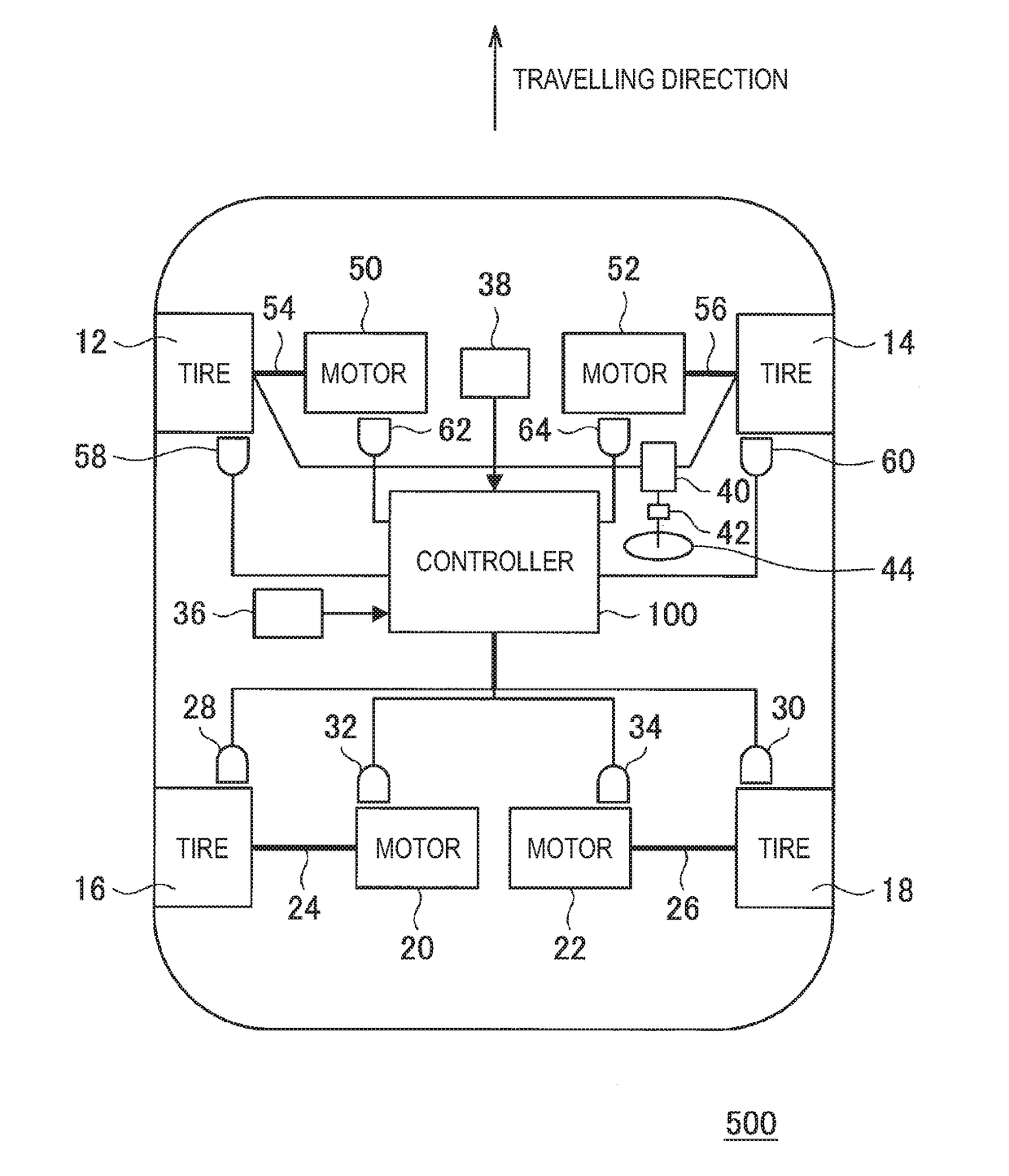
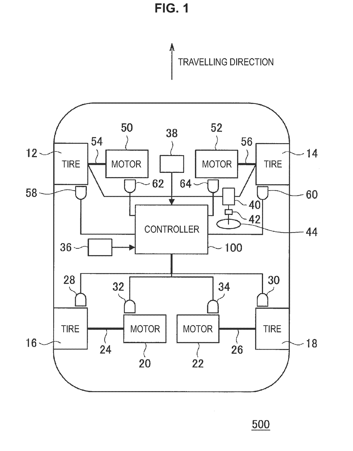
[0027]First, with reference to FIG. 1, the configuration of a vehicle 500 according to the implementation of the present invention will be described. FIG. 1 is a schematic diagram illustrating the configuration of the vehicle 500 according to the implementation of the present disclosure. As illustrated in FIG. 1, the vehicle 500 includes four tires (wheels) 12, 14, 16 and 18 including front and rear wheels, a vehicle control device (controller) 100, two motors (drive units) 20 and 22 that control the rotation of the respective rear wheel tires 16 and 18, drive shafts 24 and 26 that couple the respective ...


PUM


Abstract

A vehicle control device includes: a slip determination module that determines a slip of each of wheels; a base distribution calculation module that calculates a base distribution torque to be distributed to the front and rear wheels on the basis of requested torques and a base distribution ratio of torques between the front and rear wheels, and changes the base distribution ratio on the basis of a result of slip determination performed by the slip determination module when the slip is detected; a rotation speed control module that decreases the base distribution torque on the basis of the result of slip determination, in a manner that a rotation speed of a slipping wheel that is slipping becomes equal to a target rotation speed; and a torque vectoring module that redistributes a torque down amount of the slipping wheel to the base distribution torque of non-slipping wheels that are not slipping.

Description

CROSS-REFERENCE TO RELATED APPLICATIONS[0001]The present application claims priority from Japanese Patent Application No. 2016-034296 filed on Feb. 25, 2016, the entire contents of which are hereby incorporated by reference.BACKGROUND[0002]1. Technical Field[0003]The present invention relates to vehicle control devices and vehicle control methods.[0004]2. Related Art[0005]In the related art, for example, Japanese Unexamined Patent Application Publication (JP-A) No. 2002-067723 describes that a non-slipping wheel torque to be output to driving wheels that are not slipping is set by setting a slipping wheel torque for a driving wheel that is slipping and subtracting the slipping wheel torque from a driving axis requesting torque.[0006]However, according to the technology described in JP-A No. 2002-067723, a front shaft and a rear shaft are driven by a motor MG2 that drives the front shaft and a motor MG3 that drives the rear shaft, and it is not assumed to control torques of a front l...

Claims


Application Information

Patent Timeline
Patent Type & Authority Applications(United States)
IPC IPC(8): B60L3/10B60L15/20B60L15/02B60K1/02
CPCB60L3/102B60K1/02B60L15/20B60L2240/423B60Y2200/91B60Y2300/82B60L2240/421B60L15/025B60L2220/42B60L2220/46B60K7/0007B60K17/356B60K2007/0092B60L2240/461B60L2240/463B60L2240/465B60L2270/145B60W30/18172Y02T10/64Y02T10/72
Inventor IENAGA, HIROSHIYONEDA, TAKESHI
Owner SUBARU CORP
Why Eureka
Try Eureka