Eureka AIR delivers breakthrough ideas for toughest innovation challenges, trusted by R&D personnel around the world.

Obstacle avoidance system

a technology of obstruction avoidance and obstacle, applied in the direction of navigation instruments, using reradiation, instruments, etc., can solve problems such as obstacles other than those to be subjected to traffic control

Active Publication Date: 2017-08-17
NIHON KENKI CO LTD
View PDF0 Cites 86 Cited by
  • Summary
  • Abstract
  • Description
  • Claims
  • Application Information

AI Technical Summary

Benefits of technology

The invention allows a vehicle to safely and efficiently avoid an obstacle on a road without interfering with the driving of a vehicle in an adjacent lane. This results in improved traffic safety and efficiency.

Problems solved by technology

On a travel road, an obstacle other than those to be subjected to traffic control, such as a fallen rock or an object fallen on the travel road, may exist.

Method used


Image

  • Obstacle avoidance system
  • Obstacle avoidance system
  • Obstacle avoidance system

Examples


first embodiment

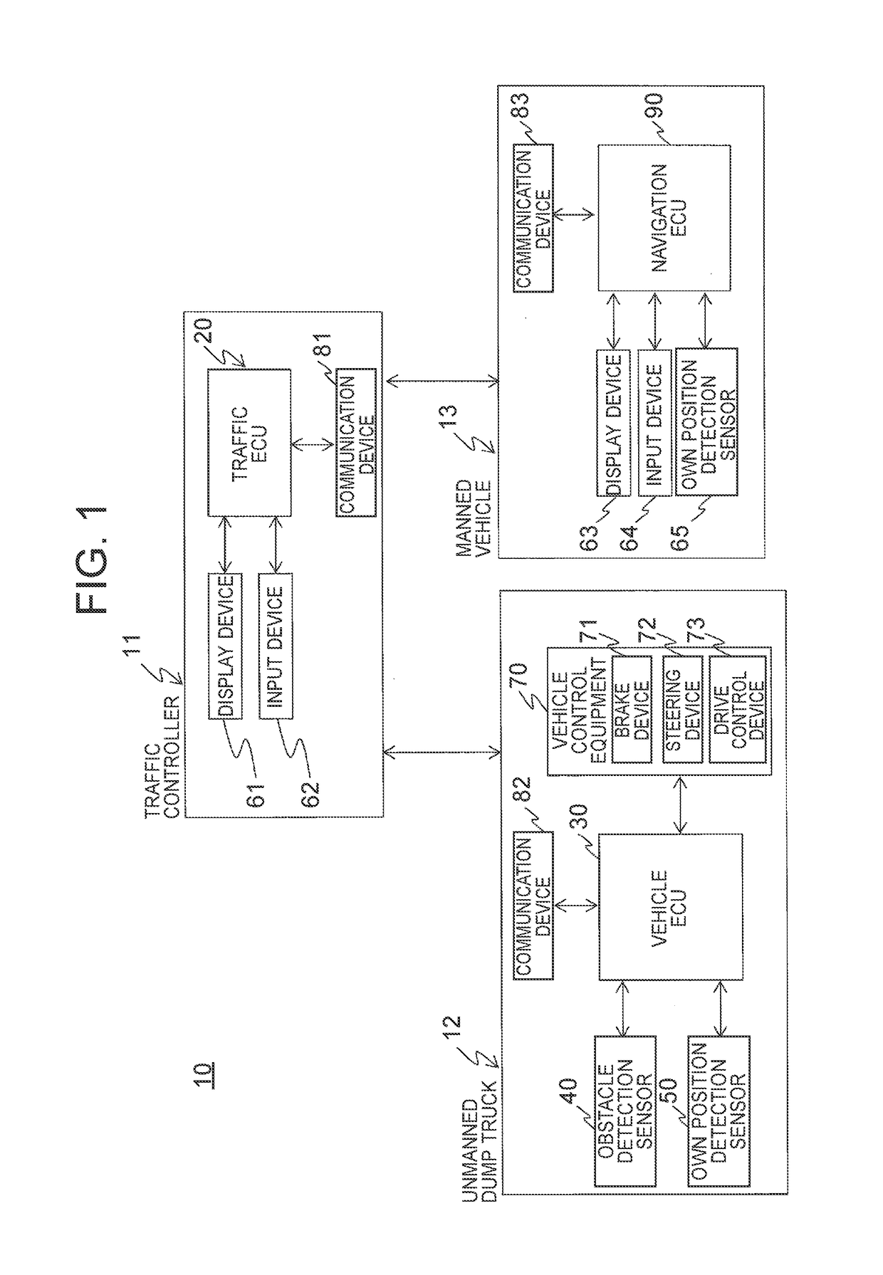
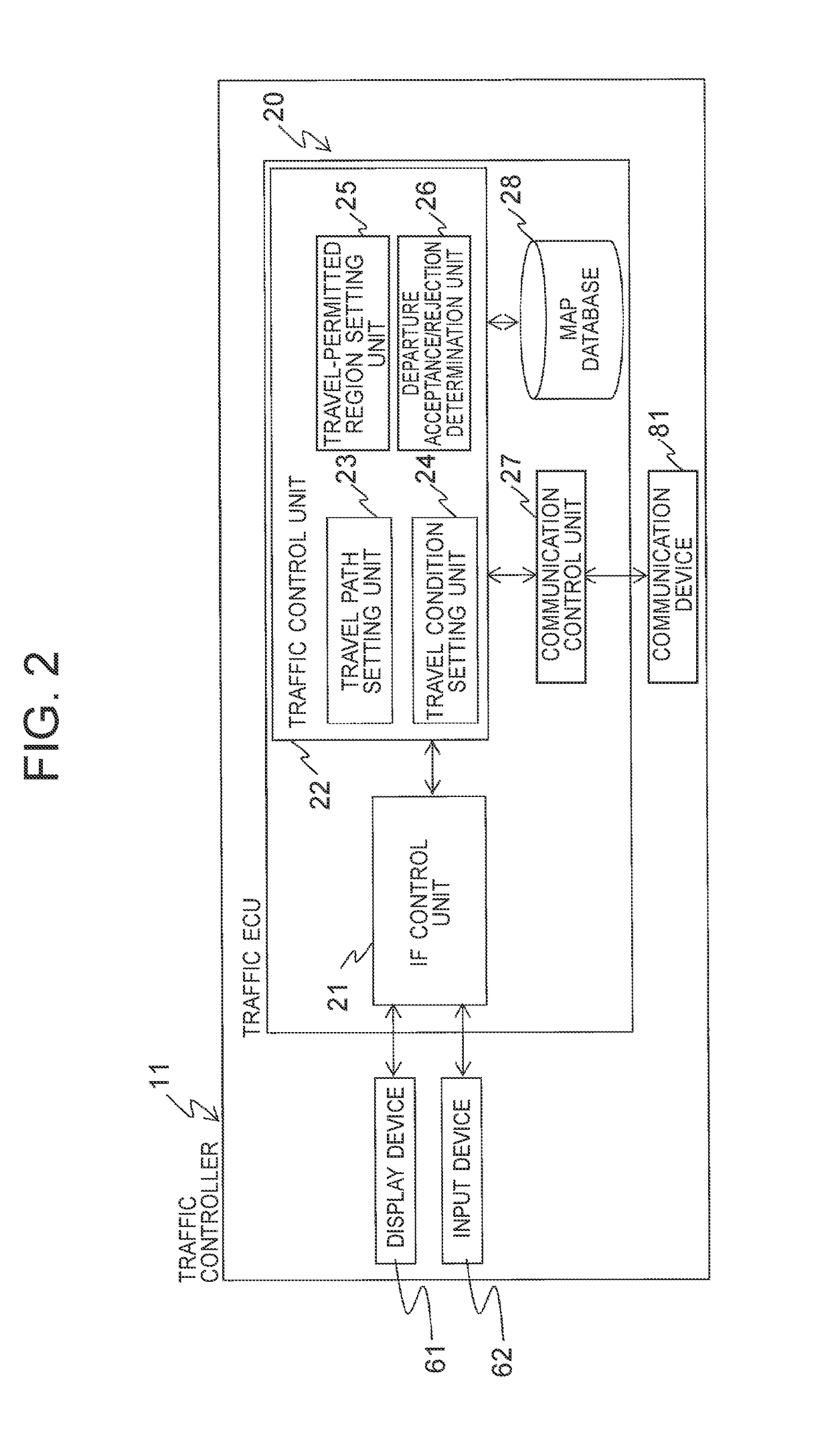
[0029]With reference to FIGS. 1 through 4, a description will be made about the schematic configuration of an obstacle avoidance system 10 according to this embodiment. FIG. 1 isaschematic diagram illustrating the configuration of an obstacle avoidance system. FIG. 2 is a block diagram illustrating the configuration of a traffic control system shown in FIG. 1. FIG. 3 is a block diagram illustrating the configuration of an unmanned dump truck shown in FIG. 1. FIG. 4 is a diagram showing illustrative map information of an approach lane and a return lane in the first embodiment.

[0030]As illustrated in FIG. 1, the obstacle avoidance system 10 according to this embodiment is configured of a traffic controller 11 and an own vehicle 12 and a manned vehicle 13, which are respectively connected for wireless communications to the traffic controller 11.

[0031]The traffic controller 11 is configured to control work contents and traveling positions and conditions with respect to each of the own v...

second embodiment

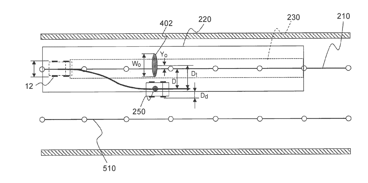
[0110]A second embodiment generates the map information of a haul road (approach lane and return lane) as one dimensional information by using only nodes and links, and performs an avoidance action of an obstacle on the basis of the results of a comparison of distances d between a target trajectory, an avoiding path, and a target trajectory in an adjacent lane. The second embodiment is different from the first embodiment in that the map information is not two-dimensional information but one-dimensional information, and the remaining elements of configuration and the flow of processing are the same, so that overlapping description is omitted. Referring to FIG. 15, a description will hereinafter be made about the generation of an avoiding path according to the second embodiment. FIG. 15 is a diagram illustrating one example of a positional relation between an own vehicle and an adjacent lane according to a second embodiment.

[0111]The map information in the second embodiment is defined...


PUM


Abstract

On a basis of a relative position of an obstacle 401, a size of the obstacle in an own vehicle 12 width direction and a width of the own vehicle 12, a maximum amount Dt of movement of the own vehicle 12 in the vehicle width direction as required to avoid the obstacle 401 is calculated. A point displaced over the maximum amount of movement toward a side of the adjacent lane from the relative position of the obstacle 401 is determined as an avoiding point 250. If a distance d between the avoiding point 250 and the adjacent lane is greater than the width Wm of the own vehicle 12, an avoiding path is generated for allowing the own vehicle 12 to pass the avoiding point 250.

Description

TECHNICAL FIELD[0001]This invention relates to an obstacle avoidance system, and especially to an avoidance system for an obstacle on a haul road with plural lanes included therein.BACKGROUND ART[0002]There is known an autonomous travel system that connects autonomously-traveling haulage vehicles (hereinafter called “unmanned dump trucks”), which can perform autonomous traveling without operators onboard, for communications with a traffic control system via a wireless communication network in an surface mine or the like. In a mining environment, unmanned dump trucks, graders and bulldozers are operated together with vehicles driven by operators (hereinafter called “manned vehicles”) such as light vehicles (for supervision or transportation of employees, etc.) and sprinkler vehicles. The traveling positions and operation conditions of these unmanned dump trucks, graders, bulldozers and manned vehicles are controlled by an autonomous travel system, and are subjected to traffic control...

Claims


Application Information

Patent Timeline
Patent Type & Authority Applications(United States)
IPC IPC(8): G08G1/16G01C21/34G01S13/931G01S17/86G01S17/931
CPCG08G1/165G01S19/13G01C21/3407G08G1/166G05D1/0257G05D1/0274G05D1/0297B60W30/09B60W30/12G08G1/16B62D15/02B62D15/0265G01S5/0072G01S13/931G08G1/207B60W30/18163G01S17/86G01S17/931B60W2554/00B60W2554/80
Inventor NAKA, TAKUYAKANAI, MASAKISATOU, TAKAYUKI
Owner NIHON KENKI CO LTD
Why Eureka
Eureka Blog
Learn More