Gripping handle for a surgical tool, and method and machine for producing such a gripping handle

Active Publication Date: 2017-08-10
IN2BONES
View PDF0 Cites 11 Cited by
  • Summary
  • Abstract
  • Description
  • Claims
  • Application Information

AI Technical Summary

Benefits of technology

[0016]Consequently, the objects assigned to the present invention aim to remedy to the different drawbacks enumerated hereinbefore and to propose a new grip

Problems solved by technology

Consequently, these known screwdrivers are generally manufactured using parts with high accuracy, and which undergo a complex and accurate assembly in order to form the handle of a screwdriver presenting the required qualities, so that they are relatively expensive and difficult to manufacture.
Moreover, the necessity to clean and sterilize the surgical instrumentation between each operation is likely to deteriorate, more or less progressively,

Method used


Image

  • Gripping handle for a surgical tool, and method and machine for producing such a gripping handle
  • Gripping handle for a surgical tool, and method and machine for producing such a gripping handle
  • Gripping handle for a surgical tool, and method and machine for producing such a gripping handle

Examples


Example

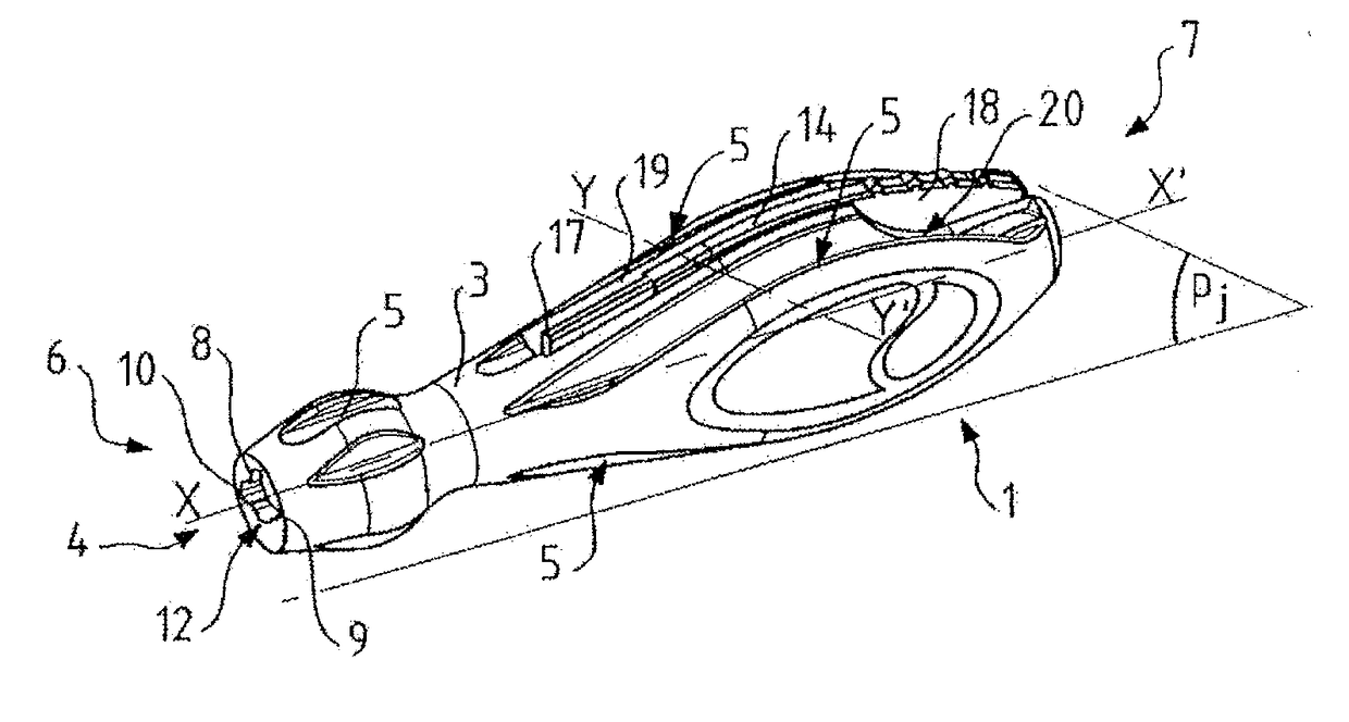
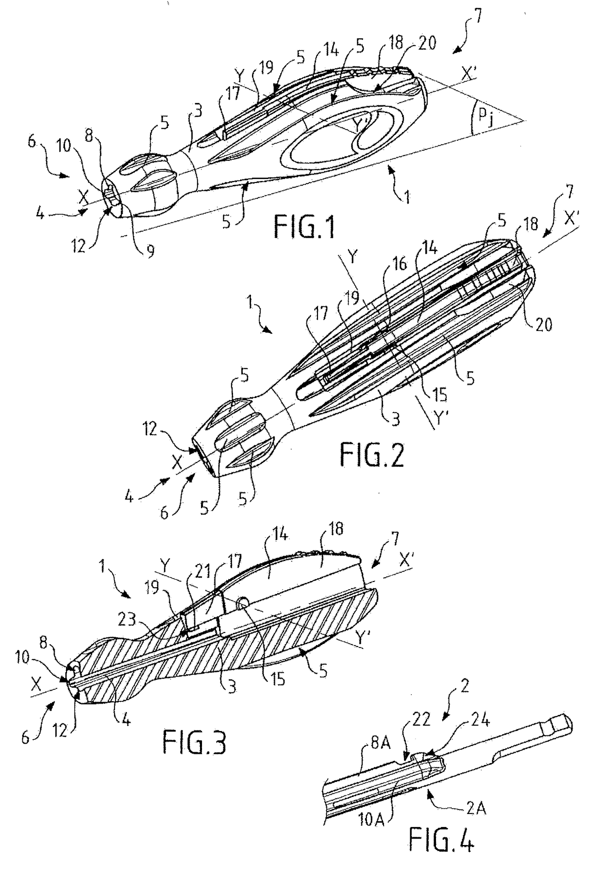
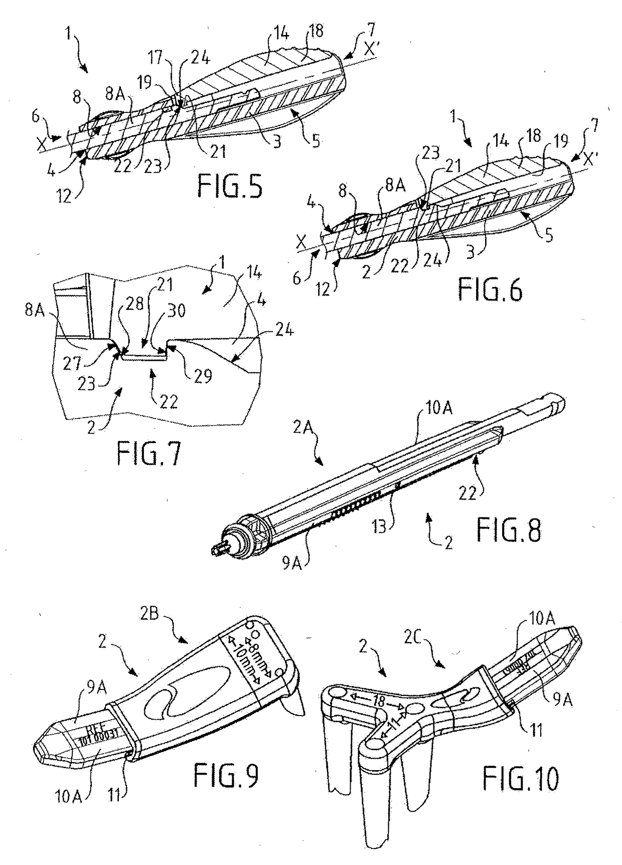
[0044]The invention concerns a part intended to participate in forming a demountable and modular surgical tool, and in this case, it concerns a gripping handle 1 of the surgical tool a first embodiment of which in accordance with the invention is illustrated in FIGS. 1 to 3, and a second embodiment in accordance with the invention is illustrated in FIGS. 11 to 13.

[0045]The gripping handle 1, which in other terms constitutes a grip or still a gripping pommel, is designed, according to the invention, to receive a removable working bit 2 in order to form a surgical tool with the latter, that is to say, in this case, a surgical instrument particularly adapted to be used by a surgeon during a surgical operation on a patient. Of course, without departing from the scope of the invention, the gripping handle 1 and the surgical tool that it participates to form may be used in the context of an animal surgery, or for uses other than surgery, for example for screwing a screw within a non-livin...


PUM


Abstract

The invention concerns a gripping handle (1) comprising:
    • a main body (3),
    • a receiving orifice (4) formed within the main body (3) for receiving a sliding removable working bit (2),
    • a blocking lever (14) rotatably mounted on the main body (3) between:
    • a blocking orientation in which it blocks the sliding of the working bit (2),
    • a release orientation in which it enables the sliding of the working bit (2),
    • an elastic pivot (15, 16) designed to bring, by itself, the blocking lever (14) back in the blocking orientation,
    • the gripping handle (1) being characterized in that the main body (3), the blocking lever (14) and the elastic pivot (15, 16) are integral with each other.
Surgical instrumentation.

Description

TECHNICAL FIELD[0001]The present invention concerns the field of surgical instrumentation, in particular surgical tools with removable or interchangeable handles, such as surgical screwdrivers with bits.[0002]More specifically, the invention concerns a gripping handle designed to receive a removable working bit in order to form a surgical tool with the latter, said gripping handle comprising:[0003]a main body extending along a longitudinal axis between a proximal end and a distal end,[0004]a receiving orifice formed within the main body and being designed to slidingly receive the working bit,[0005]a lever for blocking the sliding of the working bit in the receiving orifice, the blocking lever being rotatably mounted on the main body about an axis of rotation so as to be able to tilt between:[0006]a blocking orientation in which said lever blocks the sliding of the working bit,[0007]a release orientation in which it enables the sliding of the working bit in the receiving orifice,[000...

Claims


Application Information

Patent Timeline
IPC IPC(8): A61B17/88A61B17/28
CPCA61B17/8875B25G1/085A61B17/28A61B17/3211A61B2017/0042A61B2017/0046A61B2017/00526B25B15/02B25G1/005B25G1/066B25B23/0042B25G3/04B25G3/10B25G3/12B25G3/18B25G3/20B25G3/24B25G3/28
Inventor COILLARD-LAVIROTTE, JEAN-YVES PAUL ALBERTBOUBLIL, DANIEL EDMONDD'INGRADO, PHILIPPE EMMANUEL
Owner IN2BONES
Why Eureka
Try Eureka