
Containers shelter

Active Publication Date: 2017-07-13
MIFRAM +1
View PDF4 Cites 12 Cited by
  • Summary
  • Abstract
  • Description
  • Claims
  • Application Information

AI Technical Summary

Benefits of technology

The present invention is a shelter that is made from standard intermodal containers. These containers are commonly used for shipping goods and can be easily transported by trucks, trains, or ships. The shelter is designed to provide protection for troopers inside, with multiple barriers including steel beams, rods, or plates that can neutralize the effects of weaponry directed at the shelter. Additionally, the containers are filled with absorbing material to absorb shock waves and explosion sprays. The main benefit of this shelter is that it offers a flexible, cost-effective solution for protecting military personnel during transport.

Problems solved by technology

In this case, piling of sacks filled with earth or sand is not satisfactory since there is a need to supply enough protection from the upper side as well.
Despite the fact that these structures provide the necessary protection, they suffer from various disadvantages; they are very expensive, require a large erection time, and cannot be re-used in another site.
However, a main disadvantage of this structure is that the basic elements cannot be used directly for building a protective roof.
Furthermore, if an explosive charge falls and explodes adjacent the entrance to the protected area, there is a direct line of explosion towards the protected area.
Again, this roof is a specially built item in order to withstand the load applied thereon, and it cannot be made from the same units that form the walls.
Again, in this design, the roof cannot utilize the same units forming the walls.

Method used


Image

  • Containers shelter
  • Containers shelter
  • Containers shelter

Examples


Embodiment Construction

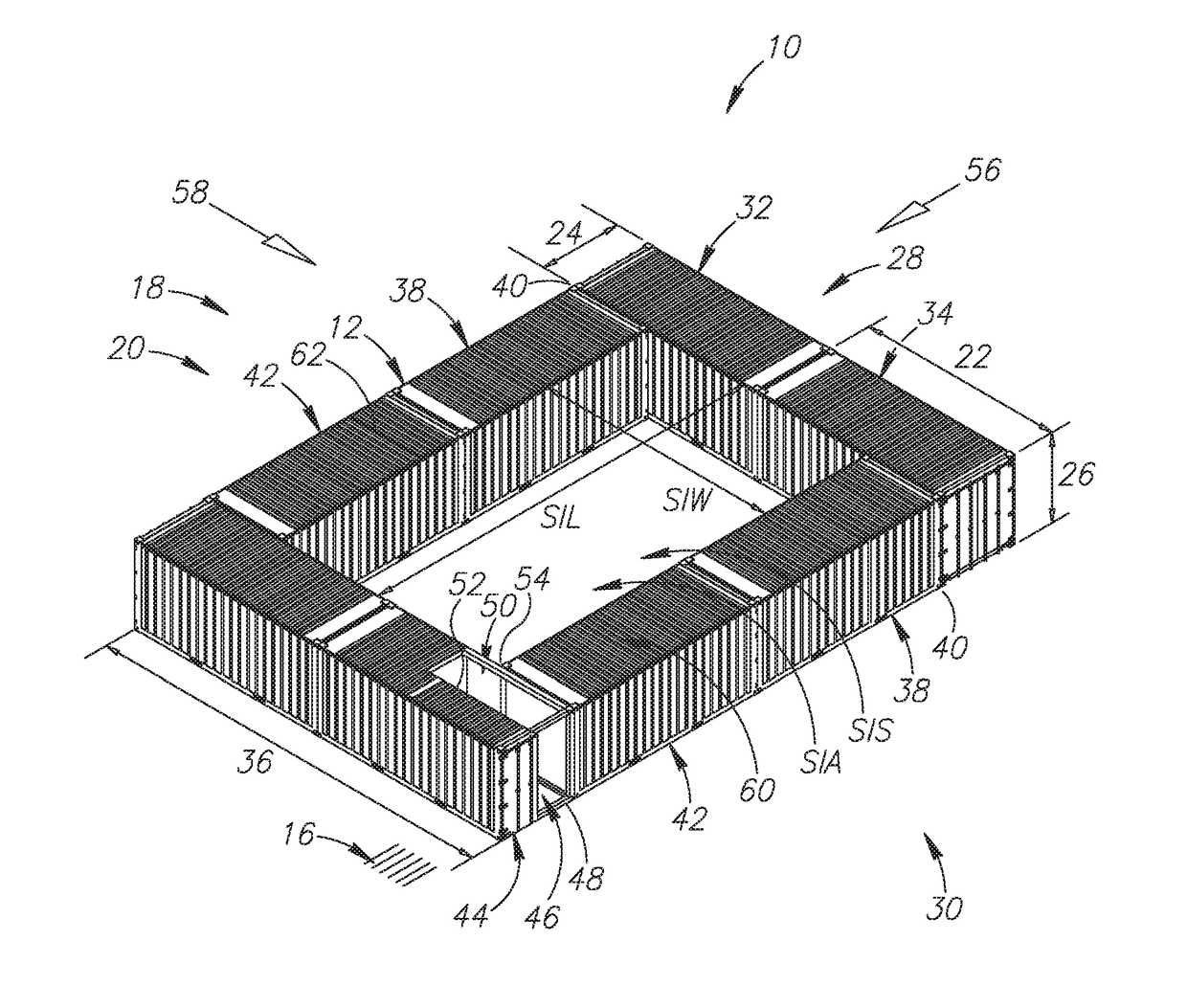
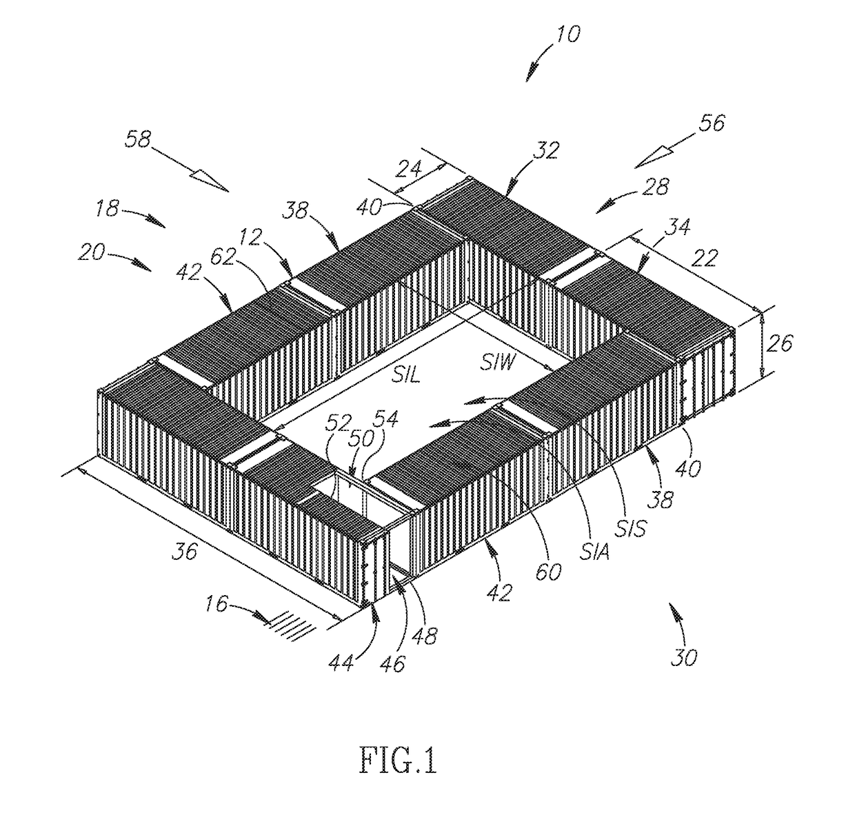
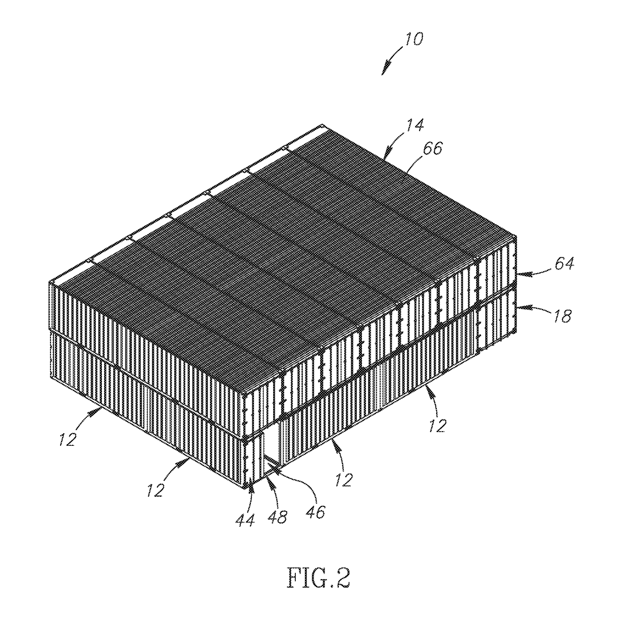
[0066]Attention is drawn to FIGS. 1-3 that show a containers shelter 10 according to the present invention. The shelter is formed from 20 ft standard intermodal containers 12 and from 40 ft standard intermodal containers 14. The containers shelter 10 is best utilized when placed on a level ground 16. The level ground 16 may be formed from a variety of substances, e.g., sand, earth, gravel, coarse sand, natural grass, grass, wood, or, concrete.

[0067]FIG. 1 shows the construction of a base floor 18 of the containers shelter 10 according to the present invention. A “base floor” means that only one level of containers is placed, without any further container placed thereon. The base floor 18 is formed from a base array 20 of 20 ft containers 12. The containers may be box containers, or, open top containers. Each 20 ft container 12 has a 20 ft container length 22, in a longitudinal dimension thereof, a 20 ft container width 24, in a width dimension thereof that is perpendicular to the lo...


PUM


Abstract

A containers shelter is formed from a base array of 20 ft containers, having a sheltered inner area therebetween, and, from a second floor of 40 ft containers that are connected to the base array of containers and cover entirely the sheltered inner area. The containers are filled with a filling material. The base array comprises an entrance container having an inner opening that is transversely directed to an outer opening.

Description

FIELD OF THE INVENTION[0001]The present invention relates to the field of human shelters erected in armed conflict zones, and more particularly to the field of shelters that can be easily erected on site in conflict zones and can contain a large number of troops.BACKGROUND OF THE INVENTION[0002]In many battle fields, when it is necessary to protect the troops, trenches are being digged, or protective walls are being erected. For many years, the protective walls were made of sacks filled with local earth or sand. This system is very cheap and easy to implement since it can be carried out by relatively small sacks that, when filled, can be easily carried out by a person. Thus, if enough sacks are piled, they enable enough protection against light and medium flat-trajectory weapons like rifles and machine guns.[0003]In many armed conflict zones around the world, there is a need to protect the military forces from being injured by steep-trajectory weapons, like rockets, missiles, and mo...

Claims


Application Information

Patent Timeline
IPC IPC(8): E04H9/10E04B1/343
CPCE04H9/10E04B1/34331E04B1/14E04H2001/1283E04B1/34384
Inventor KLEIN, AMOS
Owner MIFRAM
Learn More