
Earth Removal and Sand Mining System and Method

a technology of earth removal and sand mining, applied in the direction of mechanical machines/dredgers, soil-shifting machines/dredgers, constructions, etc., can solve the problem of difficult manipulation or repositioning of prior systems

Inactive Publication Date: 2017-07-06
CROSSWORKS LLC
View PDF3 Cites 3 Cited by
  • Summary
  • Abstract
  • Description
  • Claims
  • Application Information

AI Technical Summary

Benefits of technology

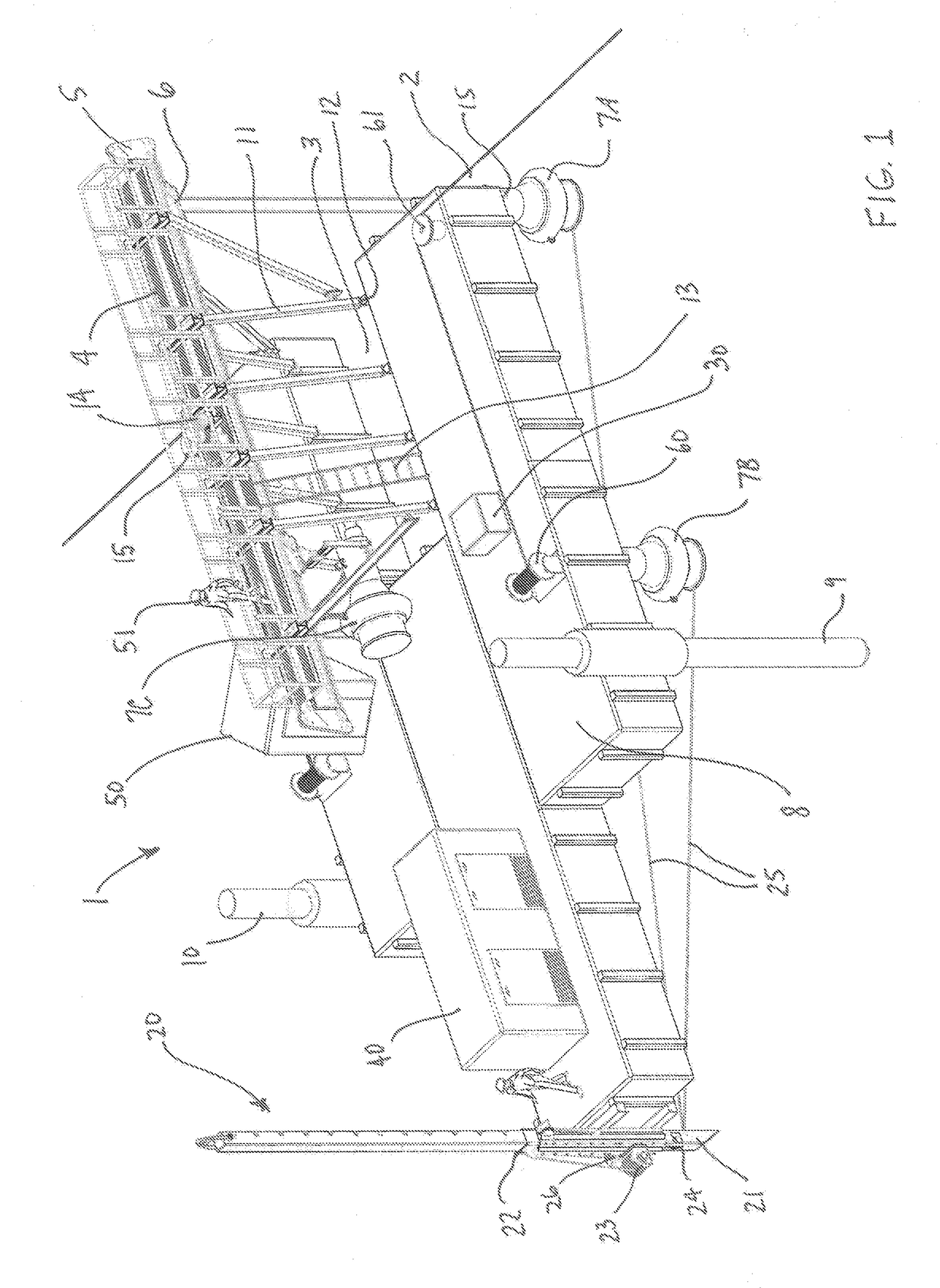
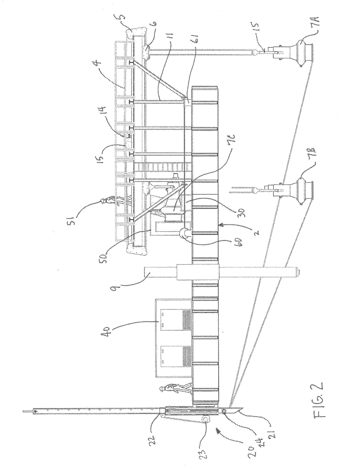
The patent describes an earth removal and sand mining system that uses a floating platform with a U-shaped open channel and a gantry positioned above it, equipped with a crane and trolley. The system also includes a hoist and a pump with a slurry discharge hose. The platform can be anchored in place using a vertical spud. The system can be powered by hydraulic or electrical power, and the trolley can move along a horizontal path parallel to the operating area. The system also includes a drag line connected to the pump and adjustable in height, which can be operated from a drag spud residing within a spud well. The platform can be pivoted in a horizontal plane around the vertical axis of the drag spud. The system is constructed from modular and interlocking floating components.

Problems solved by technology

While such systems are effective in removing earth and sand, they can be imprecise if the area being mined requires a more systematic approach or more well defined removal.
Furthermore, the prior systems can be difficult to manipulate or reposition.

Method used


Image

  • Earth Removal and Sand Mining System and Method
  • Earth Removal and Sand Mining System and Method
  • Earth Removal and Sand Mining System and Method

Examples


Embodiment Construction

[0023]Before the subject invention is further described, it is to be understood that the invention is not limited to the particular embodiments of the invention described below, as variations of the particular embodiments may be made and still fall within the scope of the appended claims. It is also to be understood that the terminology employed is for the purpose of describing particular embodiments, and is not intended to be limiting. Instead, the scope of the present invention will be established by the appended claims.

[0024]In this specification and the appended claims, the singular forms “a,”“an,” and “the” include plural reference unless the context clearly dictates otherwise. Unless defined otherwise, all technical and scientific terms used herein have the same meaning as commonly understood to one of ordinary skill in the art to which this invention belongs.

[0025]Turning now to FIG. 1, the present invention is an earth removal and sand mining system 1 for removing such mater...


PUM


Abstract

An earth removal and sand mining system is provided, comprising a modular floating platform having an elongated U-shaped open channel defining an operating area; a gantry positioned above the operating area, wherein the gantry includes a crane and trolley operable along a predefined path within the operating area; a hoist extending from the trolley; and a pump operatively suspended from the trolley, wherein the pump includes a slurry discharge hose. The platform includes an adjustable drag line connected to the pump to provide maximum control over the pump position for efficient operation.

Description

CROSS-REFERENCE TO RELATED APPLICATIONS[0001]This nonprovisional application claims priority under 35 U.S.C. 119(e) to U.S. Ser. No. 62 / 275,424, filed on Jan. 6, 2016.STATEMENT REGARDING FEDERALLY SPONSORED RESEARCH OR DEVELOPMENT[0002]Not applicable.THE NAMES OF THE PARTIES TO A JOINT RESEARCH AGREEMENT[0003]Not applicable.BACKGROUND OF THE INVENTION[0004]1. Field of the Invention[0005]The present invention relates generally to mining and dredging equipment, and more particularly to floating platforms used for earth removal and mining sand and other materials.[0006]2. Description of Related Art[0007]Conventional earth removal and sand mining from bodies of water typically requires the use of excavators positioned on the shore or on floating vessels or platforms, or heavy suction systems in similar locations. While such systems are effective in removing earth and sand, they can be imprecise if the area being mined requires a more systematic approach or more well defined removal. Fur...

Claims


Application Information

Patent Timeline
IPC IPC(8): E02F3/88
CPCE02F3/8833E02F9/065
Inventor CROSS, LESLIE M.
Owner CROSSWORKS LLC
Learn More