An aliquoting and freezing storage device
a storage device and aliquot technology, applied in the field of biological lab devices, can solve the problems of high cost, serious affecting the subsequent experimental, inspection and therapeutic effects, and the above-described process requires not only a great deal of manpower and time to complete, and the method is expensiv
- Summary
- Abstract
- Description
- Claims
- Application Information
AI Technical Summary
Benefits of technology
Problems solved by technology
Method used
Image
Examples
embodiment 1
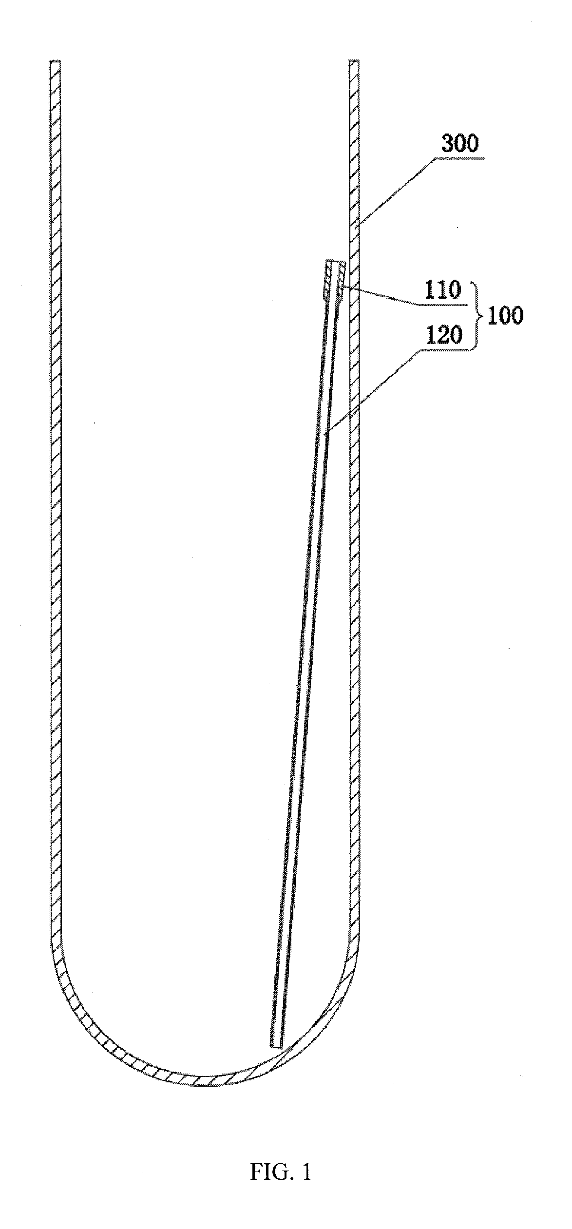
[0023]An aliquoting freezing storage device, as shown in FIG. 1, comprises a test tube 300 and at least one capillary tube 100.
[0024]The capillary tube 100 is provided with an inner elongated hole which penetrates vertically. The capillary tube 100 is inserted into the test tube 300.
[0025]Preferably, the capillary tube 100 comprises capillary tube handle 110 and a capillary body 120 disposed co-axially therewith. The capillary tube handle 110 is fixedly provided at the upper end of the capillary body 120. Further, the capillary handle 110 is mated, snap, glued or threaded to the capillary body 120. The capillary handle 110 has a pore size greater than that of the capillary body 120 and facilitates blowing of air from the top of the capillary handle 110 such that the biological sample in the capillary tube 100 flows out of the bottom of the capillary tube 100.
[0026]Preferably, the outer wall of the capillary tube 100 is coated with a non-sticking film. The non-sticking film is a plas...
embodiment 2
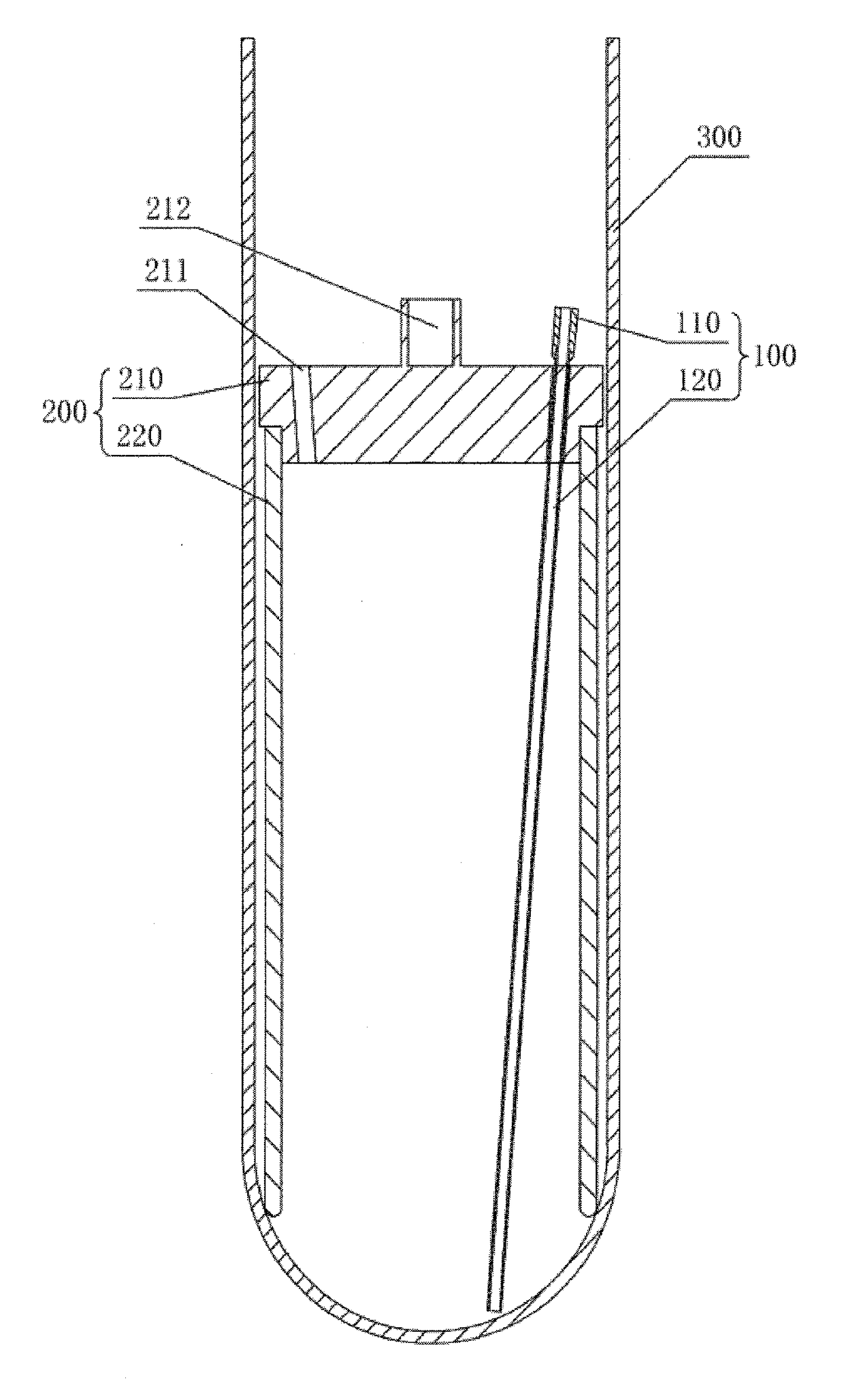
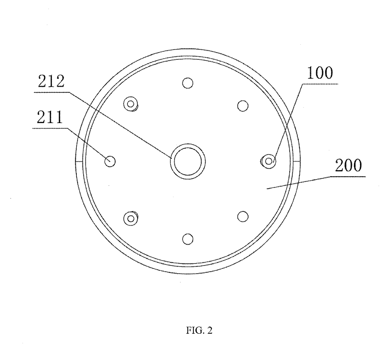
[0029]As shown in FIGS. 2 and 3, the aliquoting-freezing system comprises a test tube 300, a capillary supporter 200, and at least one capillary tube 100.
[0030]The capillary tube 100 is provided with an inner long hole which penetrates through. The capillary tube 100 is inserted into the capillary supporter 200. The capillary tube 100 includes a capillary handle 110 and a capillary body 120 disposed co-axially. The capillary handle 110 is fixedly disposed at the upper end of the capillary body 120, and preferably, the capillary handle 110 is inserted, snagged, glued, or screwed to the capillary body 120. The capillary handle 110 has a pore size greater than that of the capillary body 120 and facilitates the pipetter to blow air from the top of the capillary handle 110 such that the biological sample in the capillary tube 100 flows out of the bottom of the capillary tube.
[0031]Capillary body 120 may be any type and design of the capillary. Preferably, the capillary body 120 is a glas...
embodiment 3
[0040]In the present embodiment, as shown in FIG. 4, the capillary holder 200 includes a support plate 210 and support leg 220.
[0041]The legs 220 are at least two strips and are fixedly disposed at the outer edge of the top of the support plate 210. And the legs 220 are circumferentially surround the support plate 210. For example, when two legs 220 are provided, the two legs 220 are relatively fixed to the outer edge of the top of the support plate 210. When there are three legs 220, the three legs 220 are arranged at each apex of the equilateral triangle. The top of the leg 220 is provided with an outwardly locating hook 221. The outer diameter of the positioning hook 221 is larger than the inner diameter of the test tube 300.
[0042]At the time of installation, the positioning hook 221 is snapped at the opening of the test tube 300, thereby positioning the height of the capillary holder 200.
[0043]The rest of the present embodiment is the same as that of the embodiment 2, and will n...
PUM
 Abstract
Description
Claims
Application Information
 - R&D
- Intellectual Property
- Life Sciences
- Materials
- Tech Scout
- Unparalleled Data Quality
- Higher Quality Content
- 60% Fewer Hallucinations
Browse by: Latest US Patents, China's latest patents, Technical Efficacy Thesaurus, Application Domain, Technology Topic, Popular Technical Reports.
© 2025 PatSnap. All rights reserved.Legal|Privacy policy|Modern Slavery Act Transparency Statement|Sitemap|About US| Contact US: help@patsnap.com


