
Pneumatic tire

a technology of pneumatic tires and cylinders, which is applied in the direction of heavy-duty vehicles, vehicle components, vehicles, etc., can solve the problems of affecting the traction performance of the tire, so as to achieve excellent snow traction performance, enhance the traction performance, and ensure the traction performan

Inactive Publication Date: 2017-06-29
TOYO TIRE & RUBBER CO LTD
View PDF5 Cites 2 Cited by
  • Summary
  • Abstract
  • Description
  • Claims
  • Application Information

AI Technical Summary

Benefits of technology

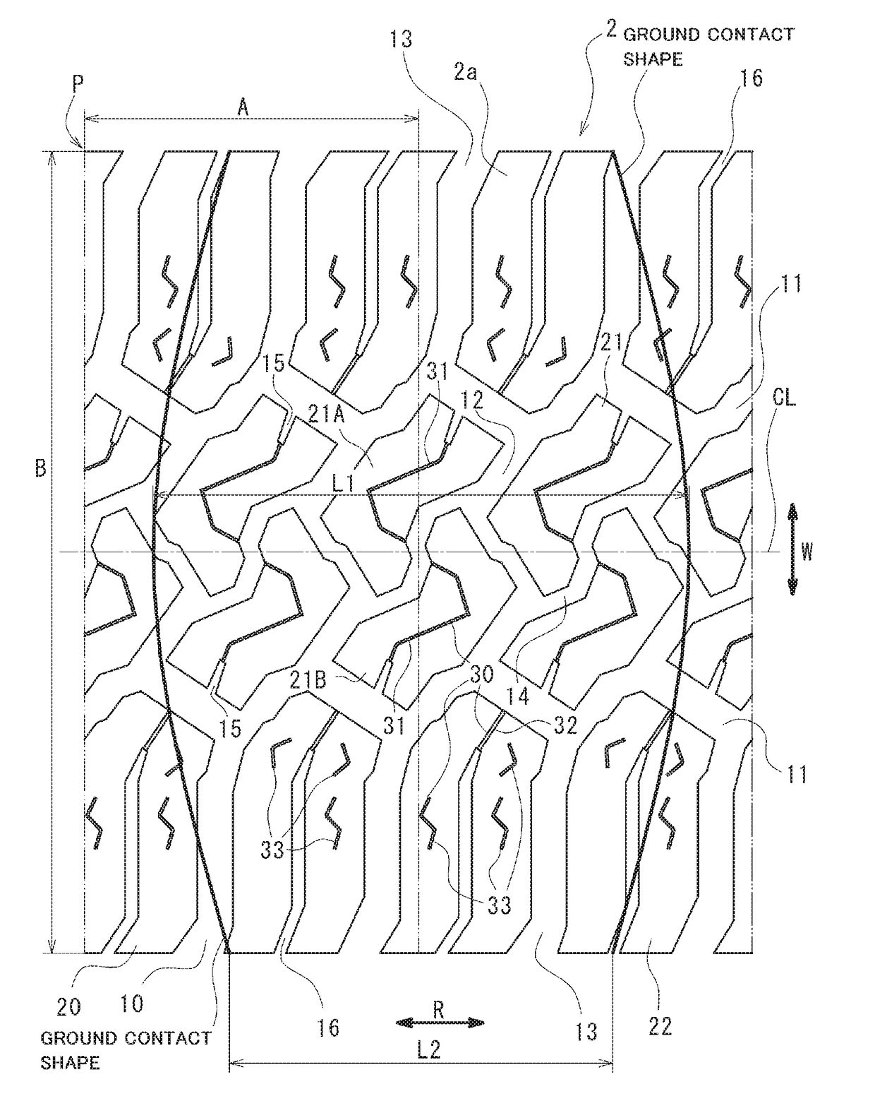
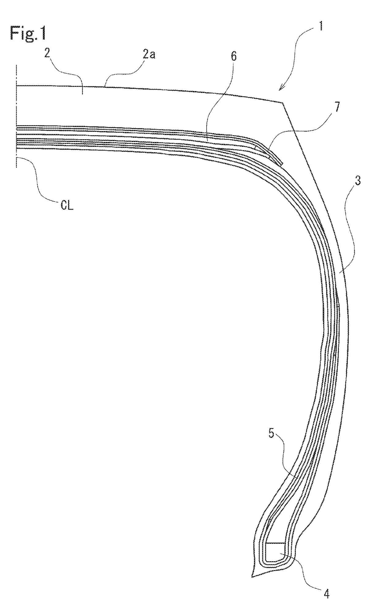
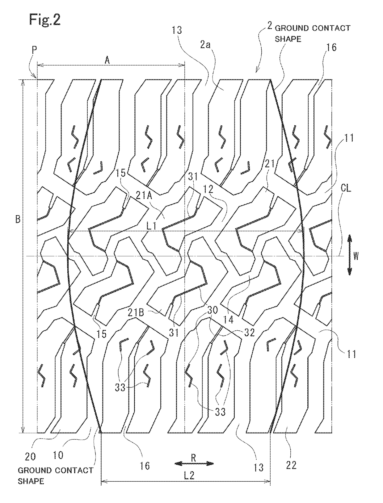
The present invention is a pneumatic tire with improved snow traction performance and external flaw resistance. It achieves this by increasing the width-direction groove component and width-direction sipe component, while also ensuring a certain see-through void. This results in a tire that can easily enhance snow traction performance while suppressing external flaw resistance deterioration. It can be used as a tire for truck winch or a tire for a light truck where its input is large. Overall, this patent improves the performance of tires in snow-covered roads and enhances their safety and reliability.

Problems solved by technology

However, when the large number of sipes are formed on each block portion, the rigidity of the block portion is largely and easily lowered.
Particularly, with respect to a pneumatic tire for a light truck having a high internal pressure and a high load, chippings or cracks are liable to occur in the block portions and hence, external flaw resistance is deteriorated.
When a width-direction groove component is less than 0.010 mm / mm2, the traction performance is liable to become insufficient.

Method used


Image

  • Pneumatic tire
  • Pneumatic tire
  • Pneumatic tire

Examples


example

[0065]Tests for evaluating external flaw resistance, snow traction performance and wear resistance were carried out with respect to pneumatic tires of comparison examples 1 to 4 and pneumatic tires of examples 1 to 3 shown in the following Table 1.

TABLE 1ComparativeComparativeComparativeComparativeExample 1Example 2Example 3Example 4Example 1Example 2Example 3LGD0.0100.0400.0400.0400.0400.0300.020(mm / mm )LSD0.0150.0150.0100.0320.0140.0150.015(mm / mm2)CGD0.0120.0120.0120.0120.0140.0150.015(mm / mm2)CSD0.0100.0100.0100.0200.0100.0100.010(mm / mm2)ASD0.0130.0130.0100.0260.0120.0130.013(mm / mm2)LGD / CGD0.83.33.33.32.92.01.3LGD / LSD0.72.74.01.32.92.01.3External⊙⊙⊙X◯⊙⊙flawresistanceSnow100130130130130120110tractionperformanceWear⊙XXX◯⊙⊙resistance indicates data missing or illegible when filed

[0066]In the pneumatic tire according to the comparison example 1, a width-direction groove component LGD is set to 0.010 mm / mm2 which is smaller than a lower limit value (0.012 mm / mm2) in the above-mentione...


PUM


Abstract

A pneumatic tire in a plurality of land portions formed by partitioning the tread portion by groove portions including a plurality of circumferential-direction grooves extending in a circumferential direction and a plurality of width-direction grooves extending in a width direction, and at least one sipe is formed on the land portion. Assuming a length component of the groove portion in the width direction per a unit area on an edge of a tread surface as a width-direction groove component, assuming a length component of the groove portion in the circumferential direction per the unit area on the edge of the tread surface as a circumferential-direction groove component, assuming a length component of the sipe the width direction per the unit area on the tread surface as a width-direction sipe component. The width-direction groove component is larger than the circumferential-direction groove component and the width-direction sipe component.

Description

CROSS-REFERENCE TO RELATED APPLICATIONS[0001]This application claims priority or Japanese Patent Application No.: 2015-253365 filed on Dec. 25, 2015, the content of which is incorporated herein by reference.BACKGROUND OF THE INVENTION[0002]The present invention a pneumatic tire.RELATED ART[0003]Conventionally, with respect to a pneumatic tire for a light truck, to ensure a higher internal pressure and a higher load compared to vehicle-use tire and also to ensure wear resistance, there has been adopted a pneumatic tire having a groove shape which is determined by taking into account ventilation property so as to suppress the lowering of the block rigidity or to suppress the generation of heat.[0004]For example, JP-A-2006-160195 discloses a pneumatic tire where a tread portion is partitioned into a plurality of block or by a plurality of circumferential-direction grooves extending in a circumferential direction and a plurality of width-direction grooves intersecting with the circumfer...

Claims


Application Information

Patent Timeline
Patent Type & Authority Applications(United States)
IPC IPC(8): B60C11/11B60C11/12
CPCB60C11/11B60C11/1236B60C2011/0346B60C2011/0365B60C2011/0353B60C11/033B60C2011/1254B60C2200/06
Inventor NAKAMURA, YUICHI
Owner TOYO TIRE & RUBBER CO LTD
Learn More