Fluid interface devices with stabilization features as well as airfoil assemblies including same

a technology of fluid interface and stabilization feature, which is applied in the direction of airflow influencers, machines/engines, transportation and packaging, etc., can solve the problems of disadvantageous conditions, band migration, physical contact could disadvantageously occur between an outside edge of the moving band,

Inactive Publication Date: 2017-06-22
ECOLOGICAL ENERGY
View PDF44 Cites 5 Cited by
  • Summary
  • Abstract
  • Description
  • Claims
  • Application Information

AI Technical Summary

Benefits of technology

The present patent describes a fluid interface device and an airfoil assembly that can be used in gaseous fluids, such as air or wind, to facilitate the flow of the fluid across the airfoil assembly. The fluid interface device includes a roller and a movable band that can be displaced in relation to the airflow direction. The airfoil assembly includes an airfoil structure with the fluid interface device attached to it. The airfoil structure has a first and second longitudinal edge and the fluid interface device includes a first and second roller that can be spaced in relation to the edges. The airfoil assembly can also include a cover wall to cover a section of the exterior surface of the movable band. The present patent also describes an airplane and a wind turbine that use the airfoil assembly. The technical effect of the invention is to facilitate the flow of fluid across the airfoil assembly and to stabilize the assembly during operation.

Problems solved by technology

In practice, however, it has been found that such moving bands may tend to migrate laterally to one side or the other as a result of various forces and / or misalignments that may be induced or otherwise occur during use.
Such migration can undesirably result in the occurrence of disadvantageous conditions associated with the moving band.
As one example, physical contact could disadvantageously occur between an outside edge of the moving band and an adjacent airfoil structure or other component associated therewith.
In some cases, such physical contact could result in reduced performance and / or the occurrence of other undesirable characteristics associated with the operation of the fluid interface device.

Method used

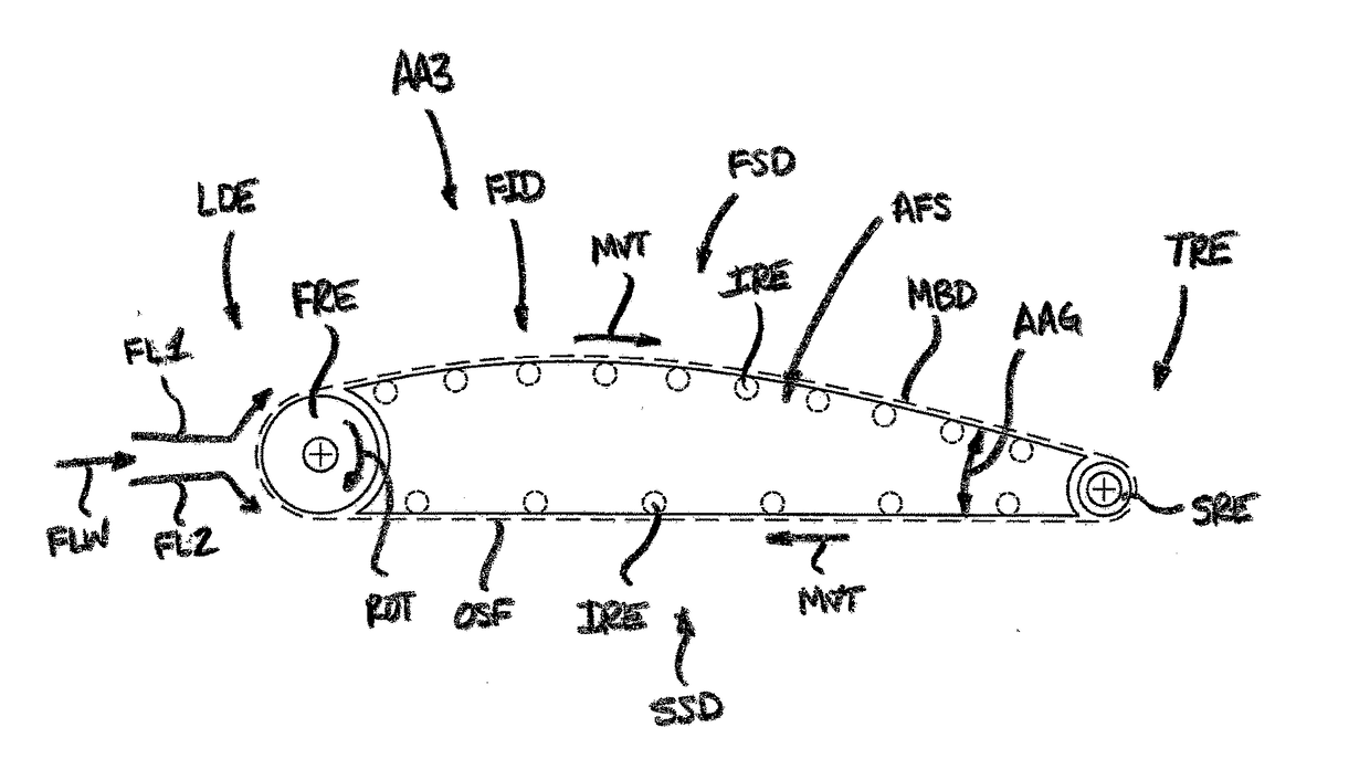
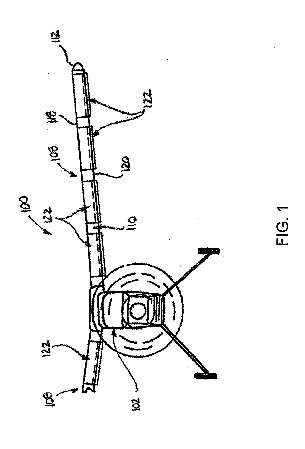
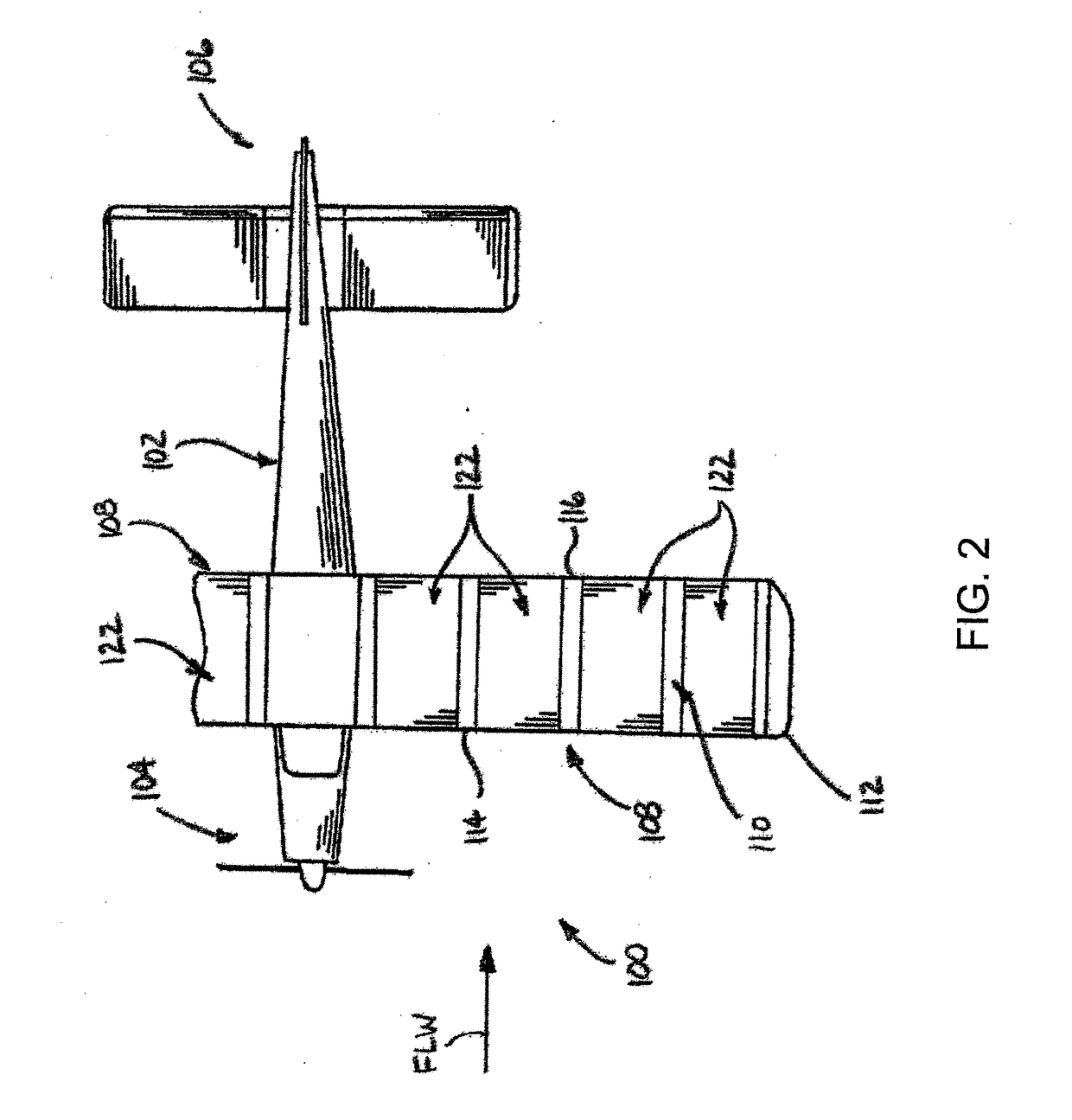

Image

  • Fluid interface devices with stabilization features as well as airfoil assemblies including same
  • Fluid interface devices with stabilization features as well as airfoil assemblies including same
  • Fluid interface devices with stabilization features as well as airfoil assemblies including same

Examples


Embodiment Construction

[0037]Referring now in greater detail to the drawings, it is to be understood that the illustrations referenced herein are for the purposes of demonstrating examples of embodiments of the subject matter of the present disclosure and that these illustrations and examples are not intended to be in any way limiting. Additionally, it should be recognized and appreciated that the drawings are not to scale, and that the proportions and / or combinations of certain features and / or elements may be exaggerated, excluded, or isolated for purposes of clarity and ease of understanding.

[0038]An airfoil assembly together with any one or more fluid interface devices thereof, in accordance with the subject matter of the present disclosure, is generally adapted for use in association with a fluidic environment such that relative movement between the airfoil assembly (and any fluid interface devices thereof) and the associated fluid can result in a fluid flow across the airfoil assembly (and any fluid ...


PUM


Abstract

Fluid interface device, such as may be used in association with airfoil assemblies, can include at least one movable band oriented such that the band moves in a direction relative to an associated relative fluid flow. The at least one movable band can be supported such that at least a portion of an outer surface of the movable band is exposed to the associated relative fluid flow. Fluid interface devices can also include one or more lateral stabilization features operative to oppose lateral migration-inducing forces on the at least one movable band that may be experienced during use of the fluid interface device in the associated relative fluid flow. Airfoil assemblies including such fluid interface devices, as well as vehicles and a wind turbines including one or more of such airfoil assemblies are also included.

Description

[0001]This application claims the benefit of U.S. Provisional Application No. 62 / 271,202, filed Dec. 22, 2015, the contents of which is hereby incorporated herein by reference in its entirety.BACKGROUND[0002]The subject matter of the present disclosure broadly relates to the art of fluid interface devices, such as airfoil structures, for example, used in connection with the relative movement of fluid, and, more particularly, to fluid interface devices that include one or more moving bands with one or more lateral stabilization features operatively associated therewith to promote tracking and alignment during displacement and use.[0003]The subject matter of the present disclosure finds particular application and use in connection with airfoil structures, such as wings of aircrafts and blades of wind turbines, and is shown and described herein with particular reference thereto. It will be appreciated, however, that the subject matter of the present disclosure is amenable to use in a v...

Claims


Application Information

Patent Timeline
Patent Type & Authority Applications(United States)
IPC IPC(8): F03D1/06B64C23/02B64C23/00B64C3/00
CPCF03D1/0675B64C3/00B64C23/02F05B2260/966F05B2240/221F05B2240/311B64C23/005B64C3/38Y02E10/72
Inventor GARVER, THEODORE M.
Owner ECOLOGICAL ENERGY
Why Eureka
Try Eureka