
Low-current fuse stamping method

a low-current fuse and stamping technology, applied in the field of circuit protection devices, can solve the problems of difficult production of low-current fuse elements using stamping processes, damage to portions of materials that must remain intact, and extremely difficult employability, and achieve the effects of convenient, cost-effective, and convenient operation

Inactive Publication Date: 2017-06-01
LITTELFUSE INC
View PDF21 Cites 0 Cited by
  • Summary
  • Abstract
  • Description
  • Claims
  • Application Information

AI Technical Summary

Benefits of technology

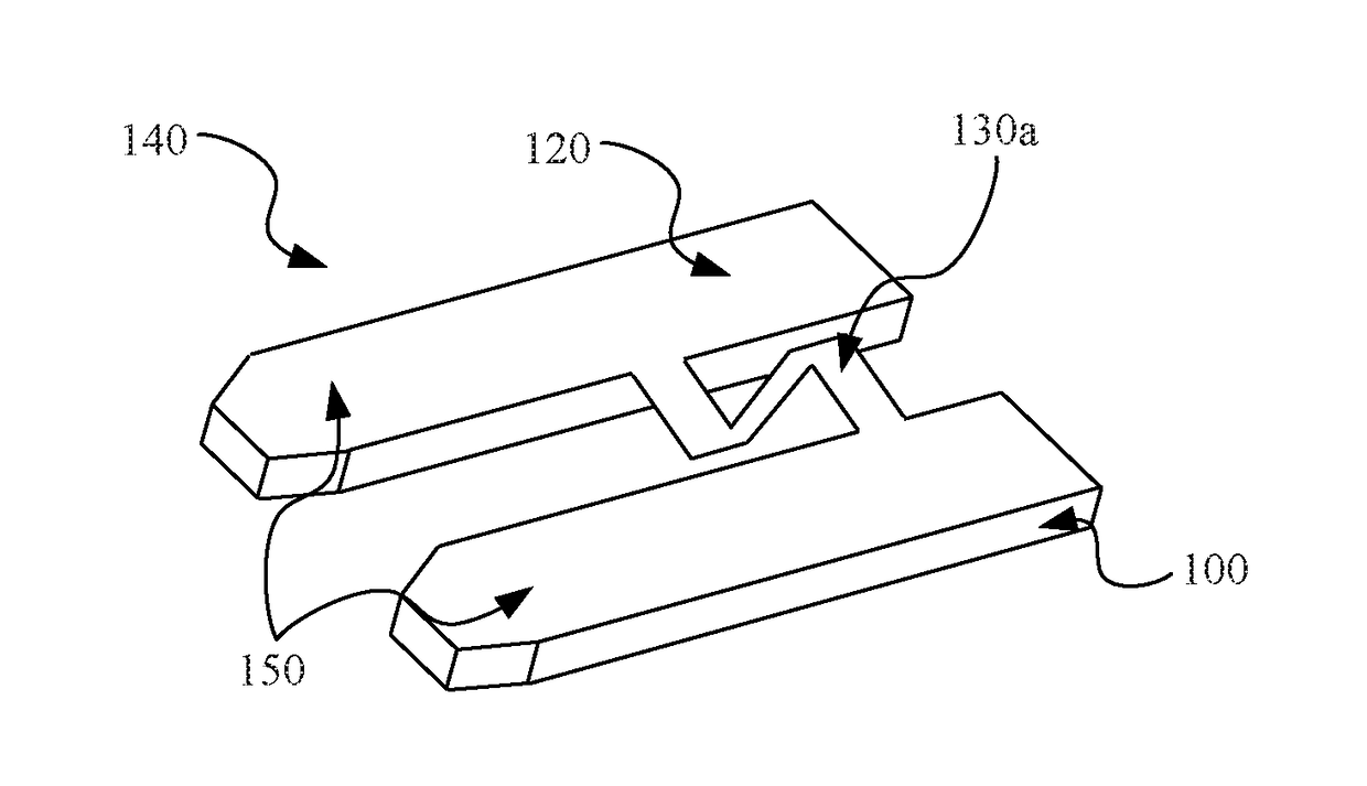
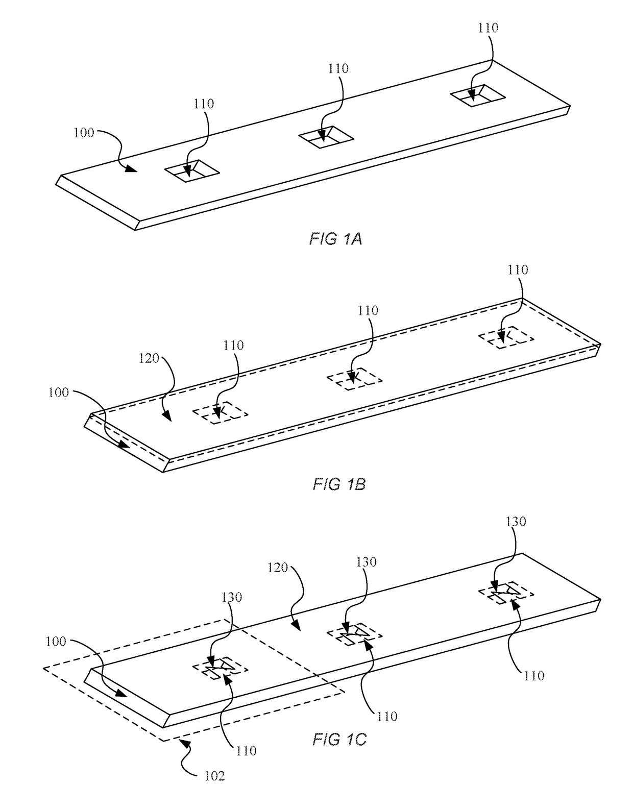
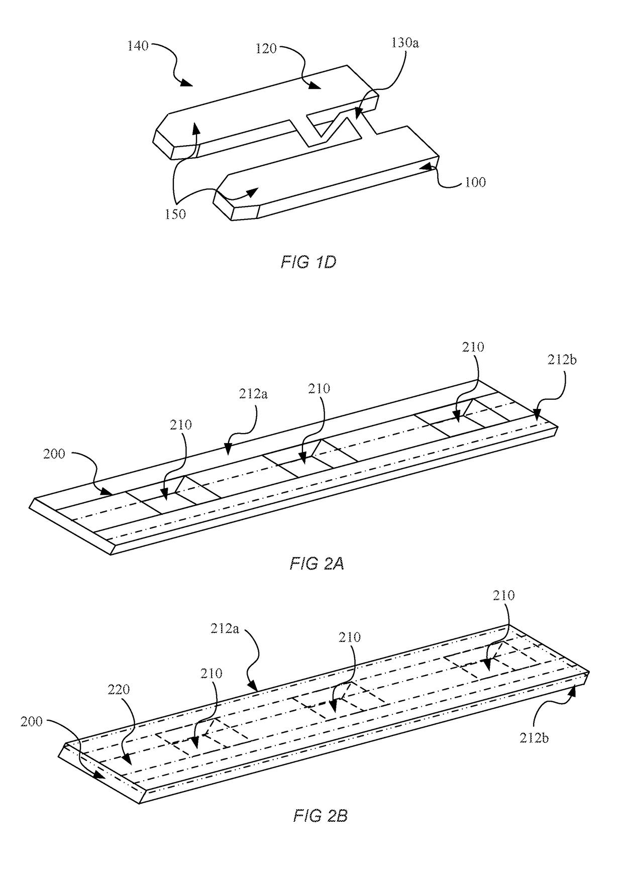
[0004]In accordance with the present disclosure, a convenient, cost-effective method for manufacturing high-quality, low-current fuse elements is provided. The method may include the steps of stamping a base metal blank out of a sheet of material and stamping at least one hole in the base metal blank. The method may further include the steps of bonding a layer of fuse material to a surface of the base metal blank with a portion of the fuse material covering the hole, stamping a fuse element out of the portion of fuse material covering the hole, and separating an individual fuse from the fuse material and the base metal blank. A low-current fuse can thereby be obtained using an easily performed, low-cost stamping process.
[0005]Additional methods may include stamping a base blank out of a nonconductive material and stamping at least one hole in the base blank. The method may further include the steps of bonding a layer of fuse material to a surface of the base blank with a portion of the fuse material covering the hole, stamping a fuse element out of the portion of fuse material covering the hole, and separating an individual fuse from the fuse material and the base blank. A low-current fuse can thereby be obtained using an easily performed, low-cost stamping process.

Problems solved by technology

However, it is extremely difficult to produce low-current fuse elements using stamping processes because such elements must generally be very narrow and very thin.
Stamping such thin materials often results in damage to portions of the material that must remain intact.
While these methods are capable of producing fuse elements that are thin and narrow, they are extremely difficult to employ and are themselves prone to material tear-through.

Method used


Image

  • Low-current fuse stamping method
  • Low-current fuse stamping method
  • Low-current fuse stamping method

Examples


Embodiment Construction

[0011]The present invention will now be described more fully hereinafter with reference to the accompanying drawings, in which preferred embodiments of the invention are shown. This invention, however, may be embodied in many different forms and should not be construed as limited to the embodiments set forth herein. Rather, these embodiments are provided so that this disclosure will be thorough and complete, and will fully convey the scope of the invention to those skilled in the art. In the drawings, like numbers refer to like elements throughout.

[0012]FIG. 1A illustrates a block diagram of a base metal blank 100. The base metal blank 100 may be stamped out of a larger sheet of material (not shown), such as a sheet of aluminum or other metal, using a conventional stamping process that will be familiar to those of ordinary skill in the art. The sheet of material may have a thickness that facilitates conventional stamping of the material. In some examples, the base metal blank 100 ma...


PUM


Abstract

A convenient, cost-effective method for manufacturing low-current fuse elements. The method may include the steps of stamping a substrate out of a sheet of material and stamping at least one hole in the substrate. The method may further include the steps of bonding a layer of fuse material to a surface of the substrate with a portion of the fuse material covering the hole, stamping a fuse element out of the portion of fuse material covering the hole, and separating an individual fuse from the fuse material and the substrate. A low-current fuse can thereby be obtained using an easily performed stamping process.

Description

CROSS-REFERENCE TO RELATED APPLICATION[0001]This application is a divisional of U.S. patent application Ser. No. 14 / 381,701 filed Aug. 28, 2014, which claims priority to U.S. Provisional Patent Application No. 61 / 647,855, filed May 16, 2012, both of which are herein incorporated by reference.FIELD OF THE DISCLOSURE[0002]The disclosure relates generally to the field of circuit protection devices and more particularly to a method for manufacturing low-current fuses.BACKGROUND OF THE DISCLOSURE[0003]Automotive fuses are typically produced using conventional stamping processes wherein a fuse is punched out of a sheet of metal by an appropriately-shaped dye. Stamping is generally preferred to other fuse manufacturing methods because it is a relatively low cost process that produces a high-quality product. However, it is extremely difficult to produce low-current fuse elements using stamping processes because such elements must generally be very narrow and very thin. Stamping such thin ma...

Claims


Application Information

Patent Timeline
Patent Type & Authority Applications(United States)
IPC IPC(8): H01H85/08H01H85/143H01H85/06
CPCH01H85/08H01H85/143H01H85/06
Inventor BECKERT, JAMES J.STUMPO, GREGORY G.SHIERRY, STEPHEN R.
Owner LITTELFUSE INC
Learn More