
Improved method for manufacturing a shell mold for production by lost-wax casting of bladed elements of an aircraft turbine engine

a technology of aircraft turbine engines and shell molds, which is applied in the direction of foundry molds, liquid fuel engines, foundry patterns, etc., can solve the problems of high labor intensity, high labor intensity, and high labor intensity, and achieve the effect of reducing the risk of shell mold blocks falling and reducing the cost of the facility

Active Publication Date: 2017-06-01
SN DETUDE & DE CONSTR DE MOTEURS DAVIATION S N E C M A
View PDF1 Cites 5 Cited by
  • Summary
  • Abstract
  • Description
  • Claims
  • Application Information

AI Technical Summary

Benefits of technology

The patent text explains a method for reducing the risks of shell mold blocks falling on the floor and the costs associated with removing them. This is achieved by improving the manufacturing process, which results in the elimination of the need for costly means of removing the blocks. This reduction in expenses reduces the overall cost of the facility used for the manufacturing process.

Problems solved by technology

During this drying, the assembly moving in the tunnel is subject to vibrations.
These blocks are then found on the floor and need to be removed, for example using costly conveyor belts.
However, these operations are also costly, and liable to involve risks in respect of health, safety and the environment (HSE risks).

Method used


Image

  • Improved method for manufacturing a shell mold for production by lost-wax casting of bladed elements of an aircraft turbine engine
  • Improved method for manufacturing a shell mold for production by lost-wax casting of bladed elements of an aircraft turbine engine
  • Improved method for manufacturing a shell mold for production by lost-wax casting of bladed elements of an aircraft turbine engine

Examples


Embodiment Construction

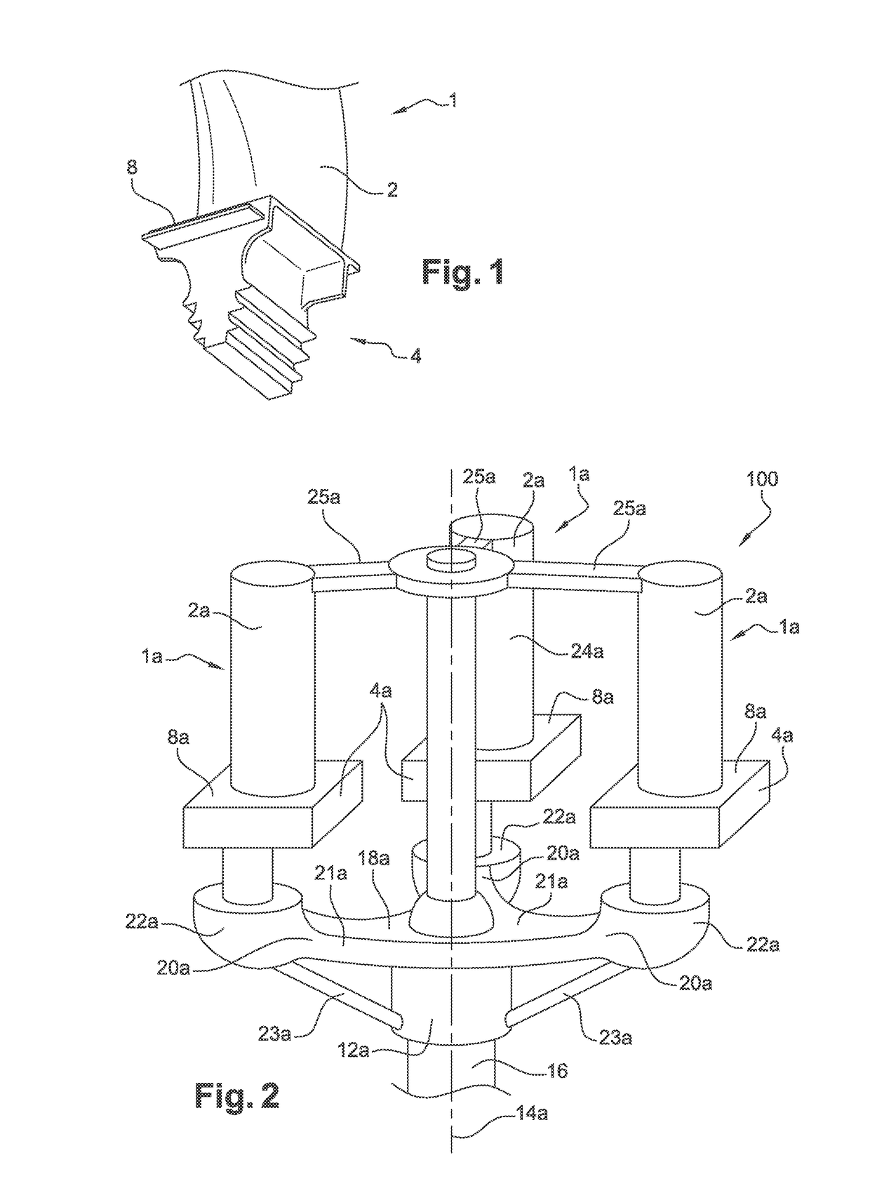
[0031]With reference to FIG. 1, an example of a mobile high-pressure turbine blade 1 for an aircraft turbine engine is represented. Conventionally, this blade 1 includes a blade 2 extending from one end 4 forming a blade root, and including a platform 8 intended to define a main gas flow jet.

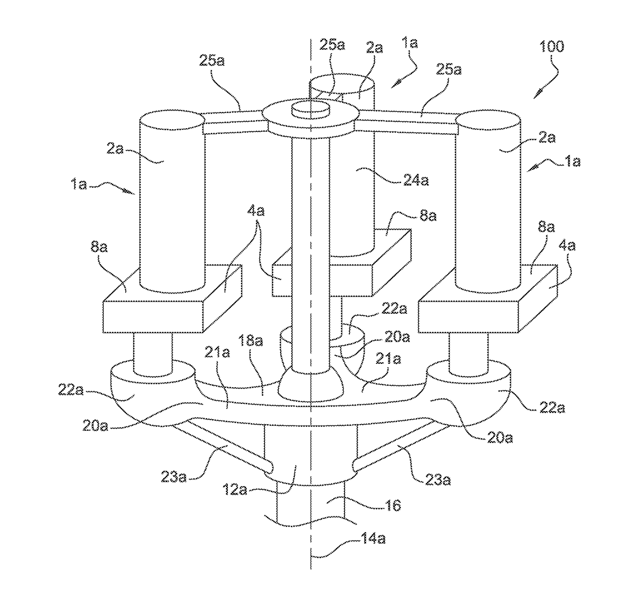
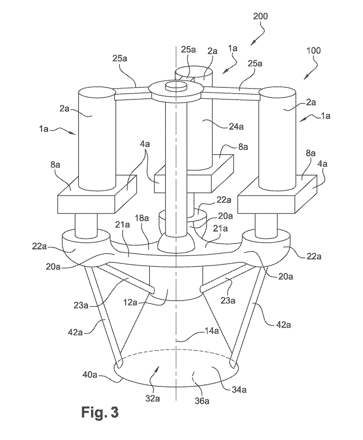
[0032]The aim of the invention is that of manufacturing the mobile blade 1 from a shell mold intended to be produced using a method specific to the invention, one preferred embodiment whereof will now be described with reference to FIGS. 2 to 10. Nevertheless, it is noted that the invention may also be applied to the manufacture of mobile compressor blades, or to the manufacture of compressor or turbine stator blades, produced separately or in sectors including a plurality of blades.

[0033]For the manufacture of the shell mold, a wax pattern is first created, also known as a replica, about which a ceramic shell mold is intended to be subsequently formed.

[0034]In FIG. 2, the wax model 100 is repre...


PUM

PropertyMeasurementUnit
temperatureaaaaaaaaaa
adhesionaaaaaaaaaa
shapeaaaaaaaaaa

Abstract

A method for manufacturing a shell mold for the production by lost-wax casting of bladed elements (1) of an aircraft turbine engine, including the following steps: creating an assembly (200) including a wax pattern (100) as well as a device for forming a cup for pouring metal (32b) and having an end surface (40a); depositing a hot wax coating layer on at least one portion of the end surface (40a); forming the shell mold around the assembly (200). In addition, the method includes, between steps b) and c), the implementation of a step of structuring the coating layer intended for reinforcing the adhesion between the layer (46) and the shell mold, and including the production of recesses (62) and projections (60) on the still-malleable coating layer.

Description

FIELD OF THE INVENTION[0001]The invention relates to the field of clustered manufacturing of bladed elements of an aircraft turbine engine, by the lost-wax casting technique. Each bladed element may be a sector comprising a plurality of blades, such as a low-pressure dispenser sector, or be an individual blade, such as a mobile compressor or turbine impeller blade.[0002]The invention relates more particularly to the manufacture of the shell mold in cluster form, wherein the metal is intended to be cast to obtain the bladed elements of the turbine engine.[0003]The invention relates to all types of aircraft turbine engines, in particular turbojets and turboprops.STATE OF THE RELATED ART[0004]From the prior art, the use of the lost-wax casting technique is known for simultaneously manufacturing a plurality of aircraft turbine engine bladed elements, such as mobile blades. Such a technique is for example described in the document FR 2 985 924.[0005]As a reminder, lost-wax precision cast...

Claims


Application Information

Patent Timeline
Patent Type & Authority Applications(United States)
IPC IPC(8): B22C9/24B22C9/10B22C9/08B22C9/04F04D29/54B05D1/18F01D5/12F01D9/02F04D29/32B22C7/02B22D25/02
CPCB22C9/24B22C7/02B22C9/103B22C9/082B22C9/04B22D25/02F05D2230/21F01D5/12F01D9/02F04D29/324F04D29/542F05D2220/323B05D1/18B22C9/043B22C9/088
Inventor MARQUES, FRANCOISDOCQUOIS, WILFRIDEBERSCHVEILLER, ERIC
Owner SN DETUDE & DE CONSTR DE MOTEURS DAVIATION S N E C M A
Learn More