Airbag Device
a technology for airbags and occupants, applied in the direction of pedestrian/occupant safety arrangements, vehicular safety arrangments, vehicle components, etc., can solve the problems of increasing the injury value of occupants, and achieve the effect of reducing the injury value, simple structure, and effective restrain
- Summary
- Abstract
- Description
- Claims
- Application Information
AI Technical Summary
Benefits of technology
Problems solved by technology
Method used
Image
Examples
first embodiment
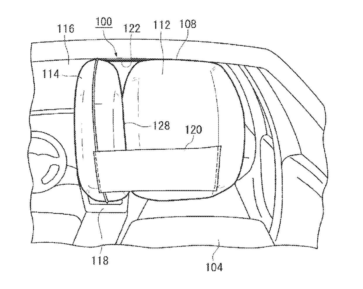
[0055]FIG. 4 is a diagram illustrating an outline of an airbag device 100 according to the present invention. FIG. 4(a) is a diagram illustrating a vehicle before operation of the airbag device 100. In the present embodiment, the airbag device 100 is embodied as an airbag device for a passenger seat. The airbag device 100 is installed on an inner side of an upper surface 106 on a side of a passenger seat 104 of an instrument panel 102.
[0056]When the airbag device 100 receives a detection signal of an impact from a sensor (not shown), a cushion 108 (refer to FIG. 4(b)) cleaves the upper surface 106 and expands and deploys toward the rear of the vehicle. FIG. 4(b) is a diagram illustrating a vehicle after operation of the airbag device 100. The cushion 108 of the airbag device 100 restrains an occupant 132 (refer to FIG. 6(a)) of the passenger seat 104 from the front of the vehicle. The cushion 108 has a bag shape and expands and deploys as gas is supplied from an inflator 110 (refer ...
third embodiment
[0111]FIG. 19 is a plan view showing a deployed state body of an airbag 518 in an airbag device according to the present invention. In the present embodiment, a sub bag area (518b) is constituted by a first chamber 518b and a second chamber 518c which are joined to left and right side parts of a main bag area 518a. The sub bag areas 518b and 518c are arranged and formed on both sides of the main bag area 518a.
[0112]The main bag area 518a and the first chamber 518b are joined by a first tether 520a and the main bag area 518a and the second chamber 518c are joined by a second tether 520b. Furthermore, the left and right first and second chambers (518b and 518c) which constitute the sub bag area are joined to each other by a third tether 520c. These three tethers 520a, 520b, and 520c are arranged so as to form an isosceles triangle, and ends of each tether are fixed by sewing to a corresponding bag.
[0113]In the present embodiment, since the sub bag areas 518b and 518c are arranged and...
fourth embodiment
[0115]First, in the fourth embodiment shown in FIG. 20(a), a point where the first tether 520a and the second tether 520b intersect each other on the main bag area 518a is offset from the line L2 toward a left side (a side of the center console). When the occupant approaches obliquely forward toward the side of the center console, spreading of the first chamber 518b can be suppressed and the head 12a of the occupant can be protected reliably.
[0116]First, in the fifth embodiment shown in FIG. 20(b), the third tether 520c according to the third embodiment described earlier is omitted. By keeping the number of tethers to a necessary minimum, a structure can be simplified and cost can be reduced. Furthermore, since sub bag areas (first and second chambers 518b and 518c) on both sides can move relatively freely towards inner sides, for example, when the head 12a of the occupant comes into contact with an inner-side surface (518′) of the left-side first chamber 518b, it is expected that t...
PUM
 Abstract
Description
Claims
Application Information
 - R&D
- Intellectual Property
- Life Sciences
- Materials
- Tech Scout
- Unparalleled Data Quality
- Higher Quality Content
- 60% Fewer Hallucinations
Browse by: Latest US Patents, China's latest patents, Technical Efficacy Thesaurus, Application Domain, Technology Topic, Popular Technical Reports.
© 2025 PatSnap. All rights reserved.Legal|Privacy policy|Modern Slavery Act Transparency Statement|Sitemap|About US| Contact US: help@patsnap.com


