
Operations Monitoring for Effect Mitigation

a technology of effect mitigation and operation monitoring, which is applied in the direction of railway signalling, transportation and packaging, instruments, etc., can solve the problems of generating significant and variable vibration, no real work exists on the ability to provide such information in real-time, and increasing the severity of the problem

Active Publication Date: 2017-04-20
INT ELECTRONICS MACHINES
View PDF1 Cites 38 Cited by
  • Summary
  • Abstract
  • Description
  • Claims
  • Application Information

AI Technical Summary

Benefits of technology

The patent text describes a system and method for monitoring and managing the effects of operations, such as train operations, that can generate impacts. The system includes sensors to collect data on the effects, an analysis tool to determine if the effects will exceed acceptable thresholds, and an initiator to take appropriate action such as alerting users or improving operational performance. The system can also manage vibration-inducing operations by setting thresholds for vibration effects and taking appropriate action such as adjusting operations or informing users. Overall, the invention helps to protect users and improve the efficiency and safety of operations.

Problems solved by technology

However, these attempts have almost universally been for evaluation and planning purposes, not for long-term, real-time monitoring and control of the environmental effects.
Because of this, no real work exists on the ability to provide such information in real-time.
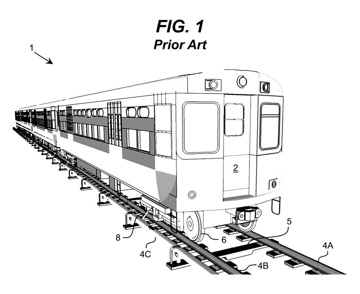
Issues of excessive sound, or noise pollution, are well-known issues of quality of life for operating rail lines as well as issues of ride quality for passengers.
However, as an increasing number of people are living near rail lines or considering using the train for their commutes, this issue is becoming far more acute.
Additionally, such trains produce significant and variable vibration and can also produce significant electromagnetic interference (EMI) from arcing or from electric drive motors operating at less than optimal levels.
In this case, vibrations of a micron or so, or extremely small variations in the electromagnetic field, can severely disrupt operations.
Disruption at the wrong time could cost immense sums of money by damaging a run of chips in a manufacturing facility or by rendering a key experiment useless.

Method used


Image

  • Operations Monitoring for Effect Mitigation
  • Operations Monitoring for Effect Mitigation
  • Operations Monitoring for Effect Mitigation

Examples


Embodiment Construction

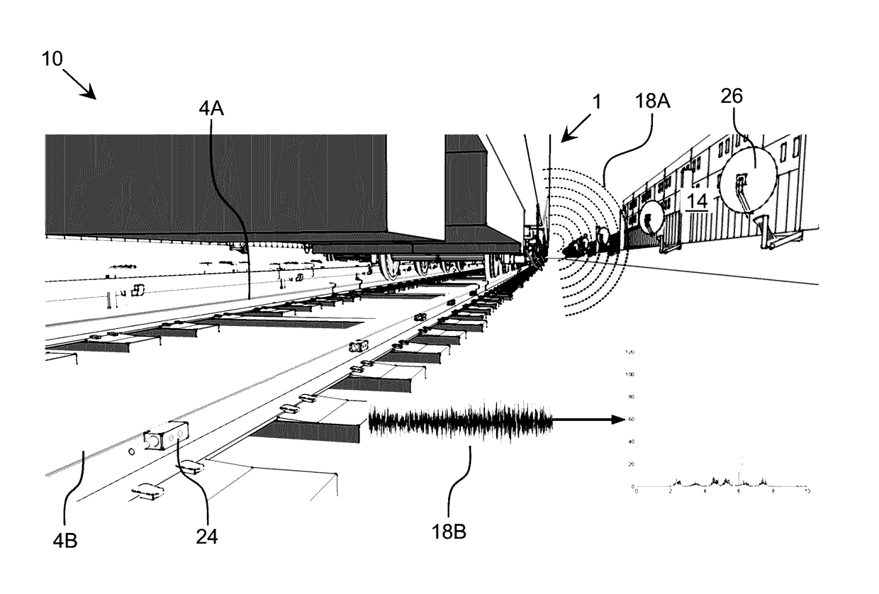
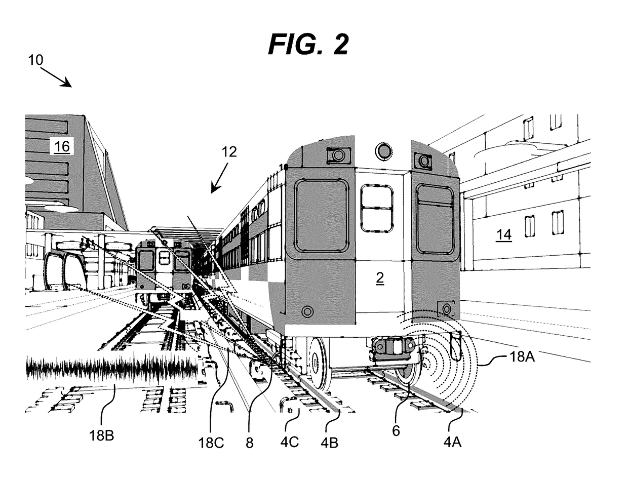
[0021]As indicated above, aspects of the invention provide a solution for managing effect-generating operations. Data regarding one or multiple types of effects being generated by the operations can be acquired and analyzed. When necessary, actions can be initiated to benefit affected individuals or to improve the operations, e.g., by mitigating a source of excessive effects. In an illustrative application, the effect-generating operations are train operations and the types of effects include acoustic and / or vibration effects. As used herein, unless otherwise noted, the term “set” means one or more (i.e., at least one) and the phrase “any solution” means any now known or later developed solution.

[0022]Current train operations monitoring systems exist which monitor the operation of the train itself. Additionally, individual systems exist to monitor very specific environmental effects, such as noise and other emissions close the rails. However, the inventors propose a solution, which ...


PUM


Abstract

A solution for managing effect-generating operations is provided. Data regarding one or multiple types of effects being generated by the operations can be acquired and analyzed. When necessary, actions can be initiated to benefit affected individuals or to improve the operations, e.g., by mitigating a source of excessive effects. In an illustrative application, the effect-generating operations are train operations and the types of effects include acoustic and / or vibration effects.

Description

REFERENCE TO RELATED APPLICATIONS[0001]The current application claims the benefit of U.S. Provisional Application No. 62 / 285,136, which was filed on 20 Oct. 2015, and which is hereby incorporated by reference.TECHNICAL FIELD[0002]The disclosure relates generally to effect-inducing operations, and more particularly, to monitoring and / or managing effect-inducing operations both for the benefit of affected individuals as well as the operating entity.BACKGROUND ART[0003]Current systems for measuring the health of components of railcars in situ through various metrology approaches and of identifying particular railcars with which to associate the health data are described in U.S. Pat. Nos. 8,925,873, 8,655,540, 8,326,582, and 8,140,250, among others. Additionally, attempts have been made to measure specific effects, such as sound levels. However, these attempts have almost universally been for evaluation and planning purposes, not for long-term, real-time monitoring and control of the en...

Claims


Application Information

Patent Timeline
Patent Type & Authority Applications(United States)
IPC IPC(8): B61L27/00B61L3/02G01V1/18B61L27/04
CPCB61L27/0094B61L27/04B61L2201/00G01V1/181B61L3/02G01V1/001G01V1/288G01H3/10B61L27/70B61L27/57
Inventor MIAN, ZAHID F.HAYES, PETER
Owner INT ELECTRONICS MACHINES
Learn More