High capacity linear valve cage

a technology of fluid regulator and linear valve cage, which is applied in the direction of fluid pressure control, process and machine control, instruments, etc., can solve the problems of high flow valve cage b, cavitation and other undesirable fluid flow issues, and allows pressure to build up insid

Inactive Publication Date: 2017-04-13
EMERSON PROCESS MANAGEMENT REGULATOR TECH INC
View PDF12 Cites 5 Cited by
  • Summary
  • Abstract
  • Description
  • Claims
  • Application Information

AI Technical Summary

Benefits of technology

[0007]In accordance with one exemplary aspect of the present invention, a control valve comprises a valve body having an inlet and an outlet, a valve seat positioned in a passageway of the valve body between the inlet and the outlet, a valve plug positioned within the valve body, and a valve cage disposed within the body adjacent the valve seat and proximate the valve plug to provide guidance for the valve plug. The valve plug is movable between a closed position, in which the valve plug sealingly engages the valve seat, and an open position, in which the valve plug is spaced away from the valve seat. The valve cage comprises a circumferential wall having an inner surface and an outer surface, a plurality of first passages formed through the circumferential wall and a plurality of second passages formed through the circumferential wall. The plurality of first passages extend between the inner surface and the outer surface and include an upper portion and a lower portion, wherein the lower portion is tapered in a direction away from the upper portion. The plurality of second passages extend between the inner surface and the outer surface and are positioned between adjacent lower portions of the first passages.

Problems solved by technology

Unfortunately, one drawback of high flow valve cage 300 is that the high initial fluid flow makes high flow valve cage 300 unstable since there is a large initial flow of fluid that surges through valve cage 300.
This can cause cavitation and other undesirable fluid flow issues.
However, one drawback of linear valve cage 400 is that in certain systems, the initial fluid flow through passages 410, which provides the stable fluid flow, is too small and allows pressure to build up within control valve 100.
This pressure build up can have undesirable affects, such as setting off safety pressure relief valves in the system due to the increased pressure, before valve plug 135 has moved far enough to allow a greater fluid flow through passages 410.

Method used


Image

  • High capacity linear valve cage
  • High capacity linear valve cage
  • High capacity linear valve cage

Examples


Embodiment Construction

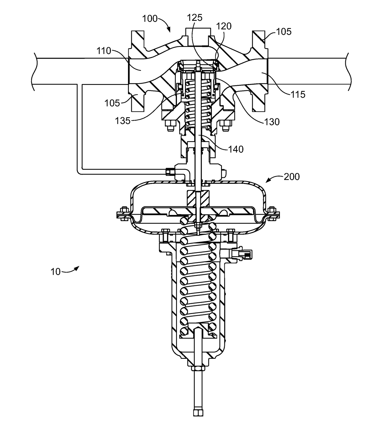
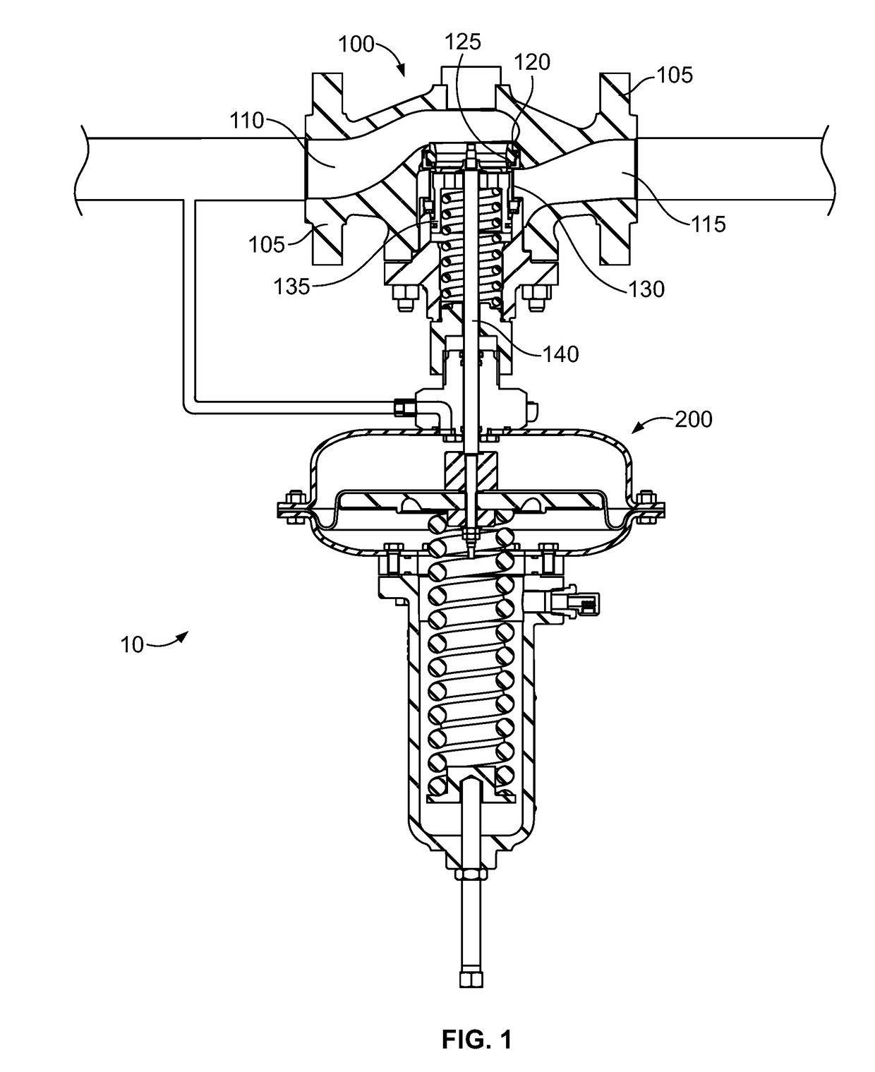
[0036]Referring to FIGS. 4-6, one example of a high capacity linear valve cage 500 is shown that can be used as valve cage 130 of control valve 100. High capacity linear valve cage 500 provides a stable initial fluid flow, much like linear valve cage 400, and also a higher capacity initial fluid flow, similar to high flow valve cage 300. The geometry of valve cage 500 allows it to be modified in increase the flow area while still maintaining stability. In addition, valve cage 500 can be tuned or custom tailored to meet specific flow requirements for individual applications.

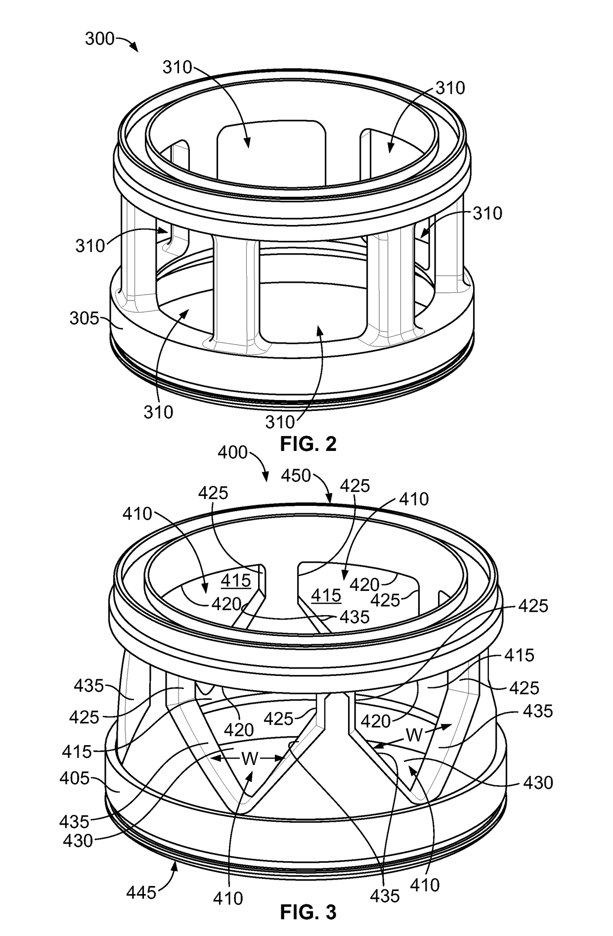
[0037]Like linear valve cage 400, valve cage 500 is cylindrical and generally includes a circumferential wall 505 forming a hollow central bore 565, within which valve plug 135 can slide to control fluid flow through valve cage 500. Circumferential wall 505 defines a top end 550, an opposing bottom end 545, an inner surface 570, and an opposing outer surface 575. First passages 510 are formed through wall 505, ext...


PUM


Abstract

A cage for a control valve has a circumferential wall having inner and outer surfaces, a plurality of first passages formed through the wall, and a plurality of second passages formed through the wall. The plurality of first passages each include an upper portion and a lower portion that is tapered in a direction away from the upper portion. The plurality of second passages are positioned between adjacent lower portions of first passages.

Description

CROSS-REFERENCE TO RELATED APPLICATIONS[0001]This application claims priority to U.S. Provisional Patent Application No. 62 / 240,089, entitled “High Capacity Linear Valve Cage” and filed Oct. 12, 2015, the entire disclosure of which is hereby incorporated by reference herein.FIELD OF THE DISCLOSURE[0002]This disclosure relates generally to fluid regulators / control valves and, more particularly, linear valve cages for fluid regulators / control valves.BACKGROUND[0003]In typical fluid regulators / control valves, a valve cage may provide guidance for a valve plug as the valve plug moves from a closed position in which the valve plug sealingly engages a valve seat to an open position in which the valve plug is disposed away from the valve seat. When the valve is in the open position, fluid flows from a valve inlet, passes through a passage between the valve seat and the valve plug, passes through the valve cage, and exits through a valve outlet. In addition to guiding the valve plug, a valv...

Claims


Application Information

Patent Timeline
Patent Type & Authority Applications(United States)
IPC IPC(8): F16K1/52F16K47/08
CPCF16K47/08F16K1/52F16K1/32F16K31/1264F16K31/1266G05D16/0658G05D16/024
Inventor REYNOLDS, MATTHEW D.MICHNEVITZ, MARK ALEXANDERBUFORD, KELLEY JAKEVASQUEZ, ERNESTO
Owner EMERSON PROCESS MANAGEMENT REGULATOR TECH INC
Why Eureka
Try Eureka