
Air Quality Test Unit and Process

a technology of air quality and test unit, applied in the direction of sampling, instruments, measurement devices, etc., can solve problems such as affecting flow, and achieve the effect of convenient us

Active Publication Date: 2017-03-30
NOVARO LUIGI +1
View PDF0 Cites 9 Cited by
  • Summary
  • Abstract
  • Description
  • Claims
  • Application Information

AI Technical Summary

Benefits of technology

The present invention provides an air quality test unit that can be positioned on a vent of a heat, ventilation, air conditioning (HVAC) system to capture and retain the airborne substances emanating from the system. The unit has two substrate panels with one panel having a sticky surface that is covered by a removable layer. The panels are held in an open v-shaped position on the vent vane by a hinge and clip combination. After use, the panels can be closed and retained all airborne substances for analysis. The invention also provides a process for measuring the air quality of the air flow emanating from the HVAC system with a laboratory analysis. The air quality test unit is easy to use, highly accurate, and can be packaged and shipped while retaining all airborne substances.

Problems solved by technology

If the panels are normal (perpendicular) to the vent air flow, this disrupts the flow.

Method used


Image

  • Air Quality Test Unit and Process
  • Air Quality Test Unit and Process
  • Air Quality Test Unit and Process

Examples


Embodiment Construction

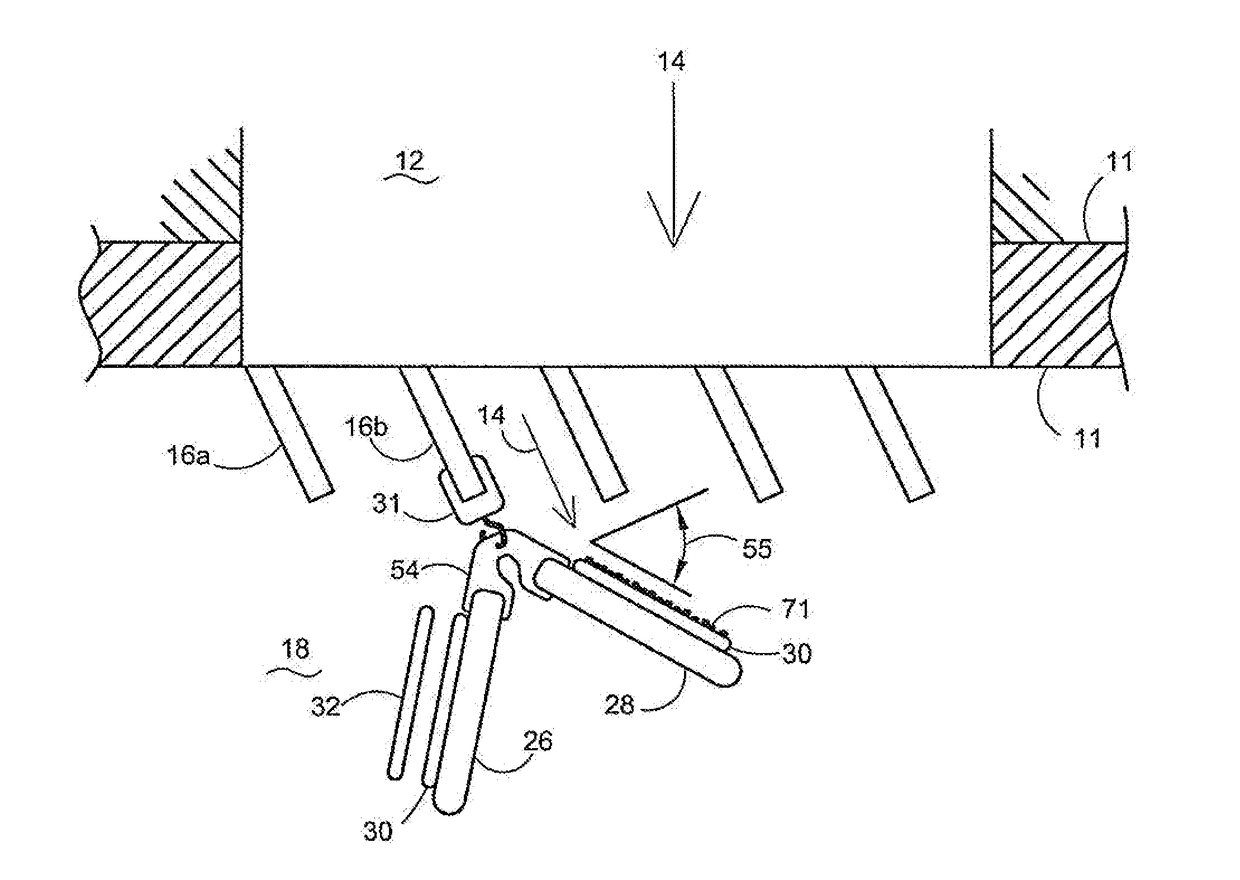
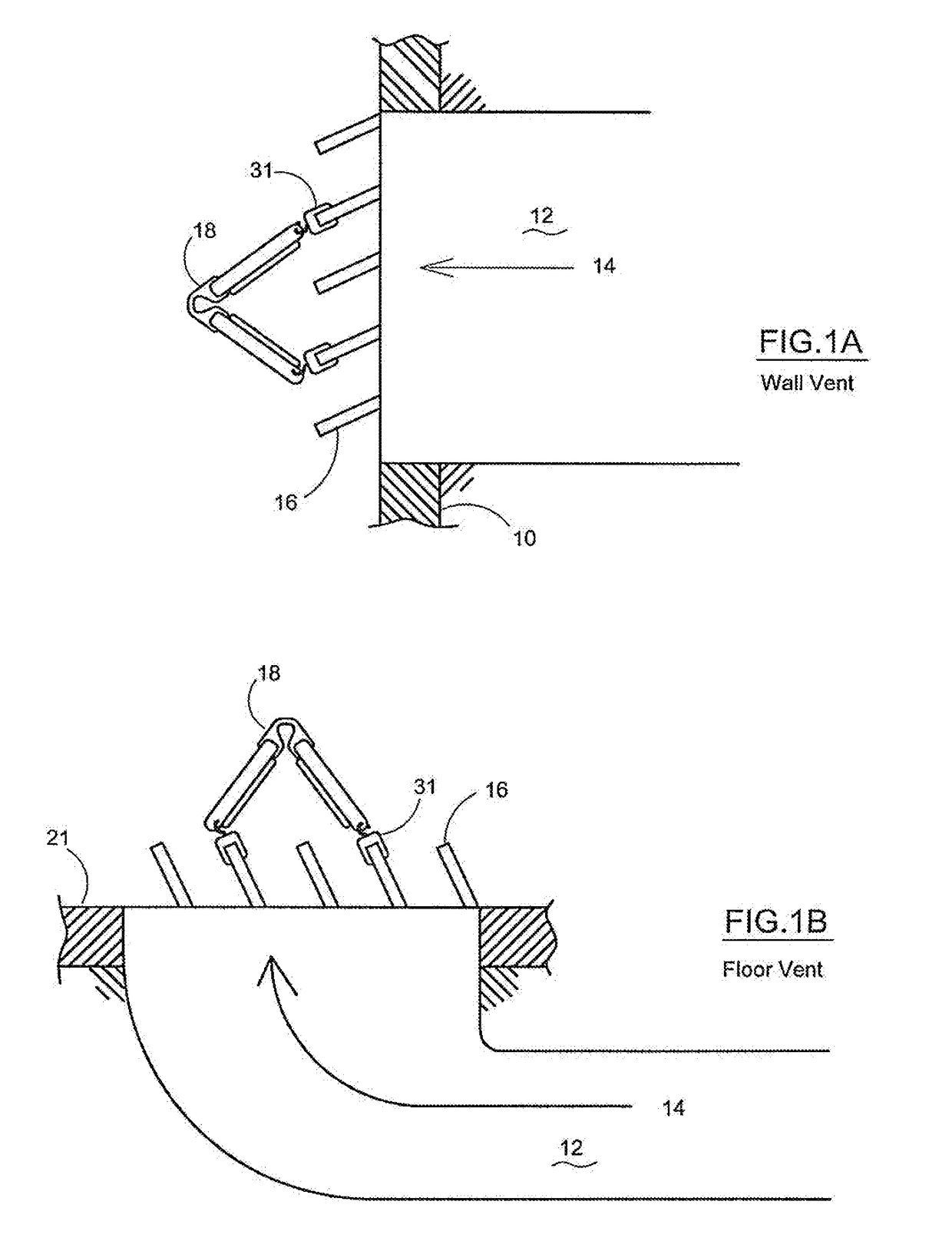
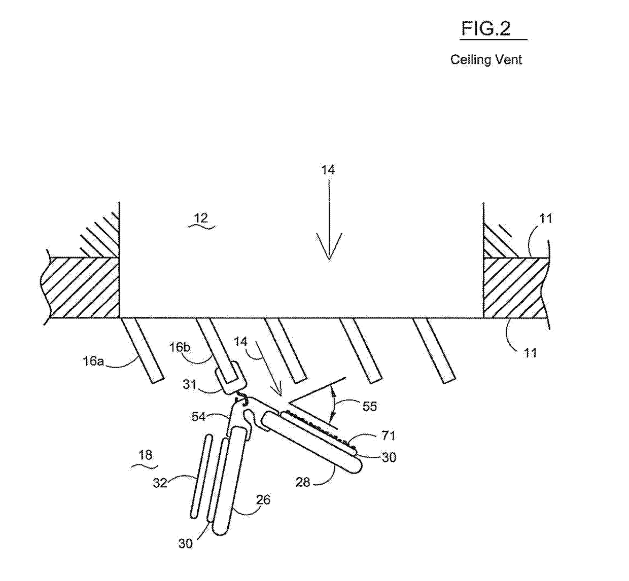
[0038]Referring now to the drawings, the invention will be described in more detail. Further objects and advantages of the present invention are illustrated in the drawings and are discussed hereinafter. Similar numerals designate similar items in the diagrammatic drawings FIGS. 1-16. It is important to note that the embodiments of the invention described below are only examples of the several advantageous uses of the innovative teachings described herein. In general, statements made in the specification of the present application do not necessarily limit any of the various claimed inventions. Moreover, some statements may apply to some inventive features but not to others. In general, unless otherwise indicated, singular elements may be in the plural and vice versa with no loss of generality.

[0039]FIG. 1A is a side view of a HVAC wall duct and vent with an air quality test unit attached to the vent blades or vent vanes. The vent blades channel air from the HVAC duct work into the i...


PUM

PropertyMeasurementUnit
angleaaaaaaaaaa
time periodaaaaaaaaaa

Abstract

An air quality test unit for attachment to a vent of a HVAC system with air flow there through. The air quality test unit is a closeable collection container is used with only one substrate panel. The substrate panel with the collection container has one or more ball and socket pivot hinges coupling the substrate panel to the clip. The air quality test unit is attachable to the vent by the clip. The collection container of the substrate panels capture airborne substances and contaminants emanating from the air flow of the HVAC system vent and is then closed with a detachable cover. A culture growth medium may be disposed in the collection container. The air quality test unit kit provides a user with an air quality test unit and process for shipping the unit to the laboratory for analysis.

Description

[0001]This is a Continuation-in-part under 35 U.S.C. §120 of non-provisional patent application Ser. No. 15 / 088,646 filed Apr. 1, 2016 entitled Air Quality Test Unit and Process that claims the benefit of an earlier filed provisional application under 35 U.S.C. §119(e) to Application No. 62 / 149,228 filed Apr. 17, 2015 the contents of which is incorporated herein by reference thereto.[0002]The present invention relates to an air quality test unit and kit for attachment to a vent of a heat, ventilation and air conditioning systems (herein “HVAC systems,” sometimes HVAC ducts only carry heated air and not AC flows). The air quality test unit is attachable to the vent blades of a vent from which air flows there through. The air quality test unit includes at least two substrate panels with at least one sticky surface or at least one collection container, and which attaches to a vent blade by one or more clips. The substrate panels take a v-shape form and the sticky surface or the collect...

Claims


Application Information

Patent Timeline
Patent Type & Authority Applications(United States)
IPC IPC(8): G01N1/22G01N33/00
CPCG01N1/2247G01N2001/227G01N33/0011G01N15/0606G01N2001/2223G01N2015/0046
Inventor NOVARO, LUIGI
Owner NOVARO LUIGI
Learn More