
Mechanical locking system for building panels

a technology of locking system and building panel, which is applied in the direction of dismountable cabinets, book cabinets, furniture parts, etc., can solve the problem of inability to disassemble, and achieve the effect of simplifying the disassembly of panels

Active Publication Date: 2017-03-30
VÄLINGE INNOVATION AB
View PDF2 Cites 62 Cited by
  • Summary
  • Abstract
  • Description
  • Claims
  • Application Information

AI Technical Summary

Benefits of technology

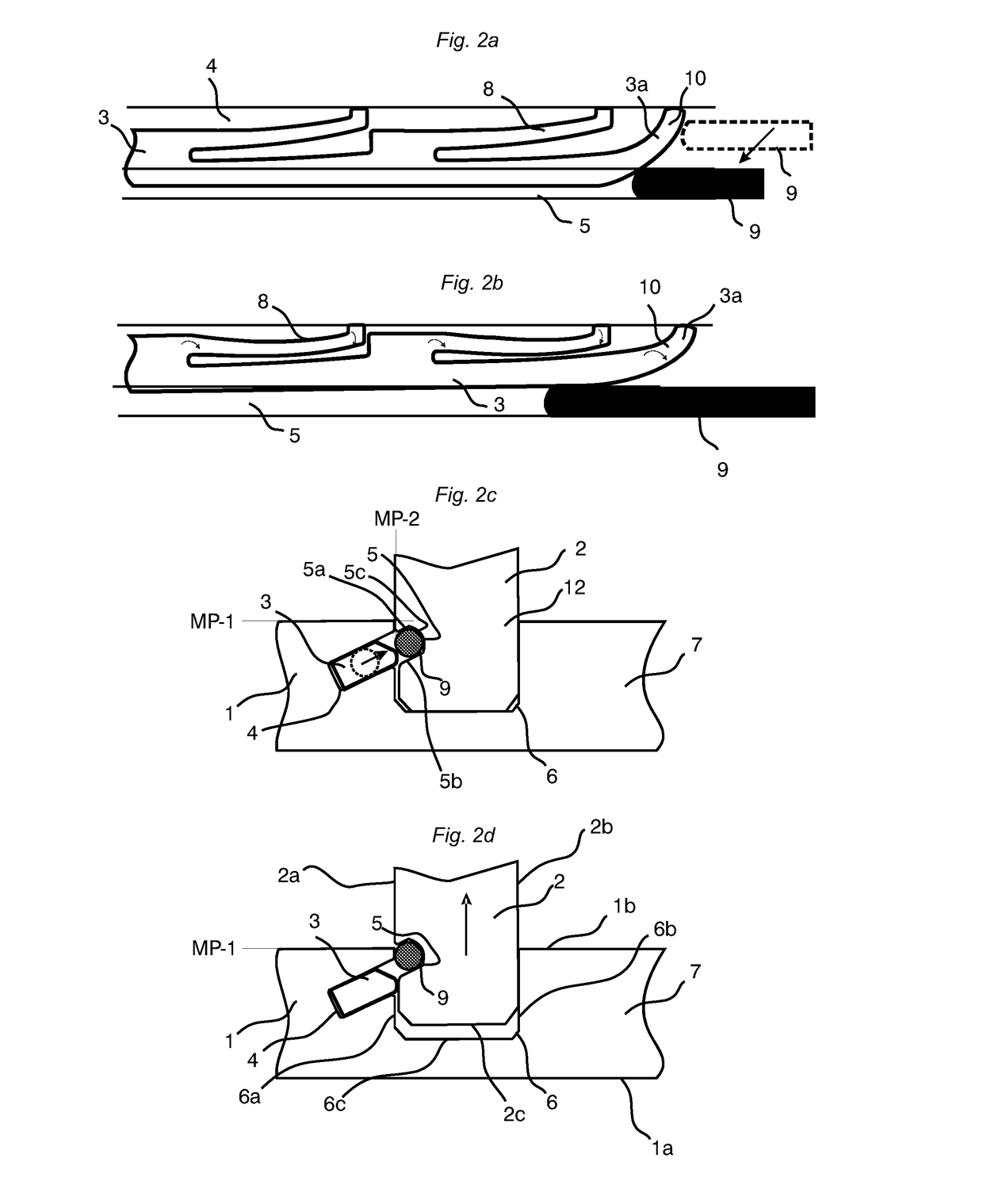
The invention allows for easier disassembly of panels because the rod shaped tool can be inserted sideways into the insertion groove and automatically guided into the tongue groove. The tool has a simple round cross section, which makes it easy to insert and disassemble the panels.

Problems solved by technology

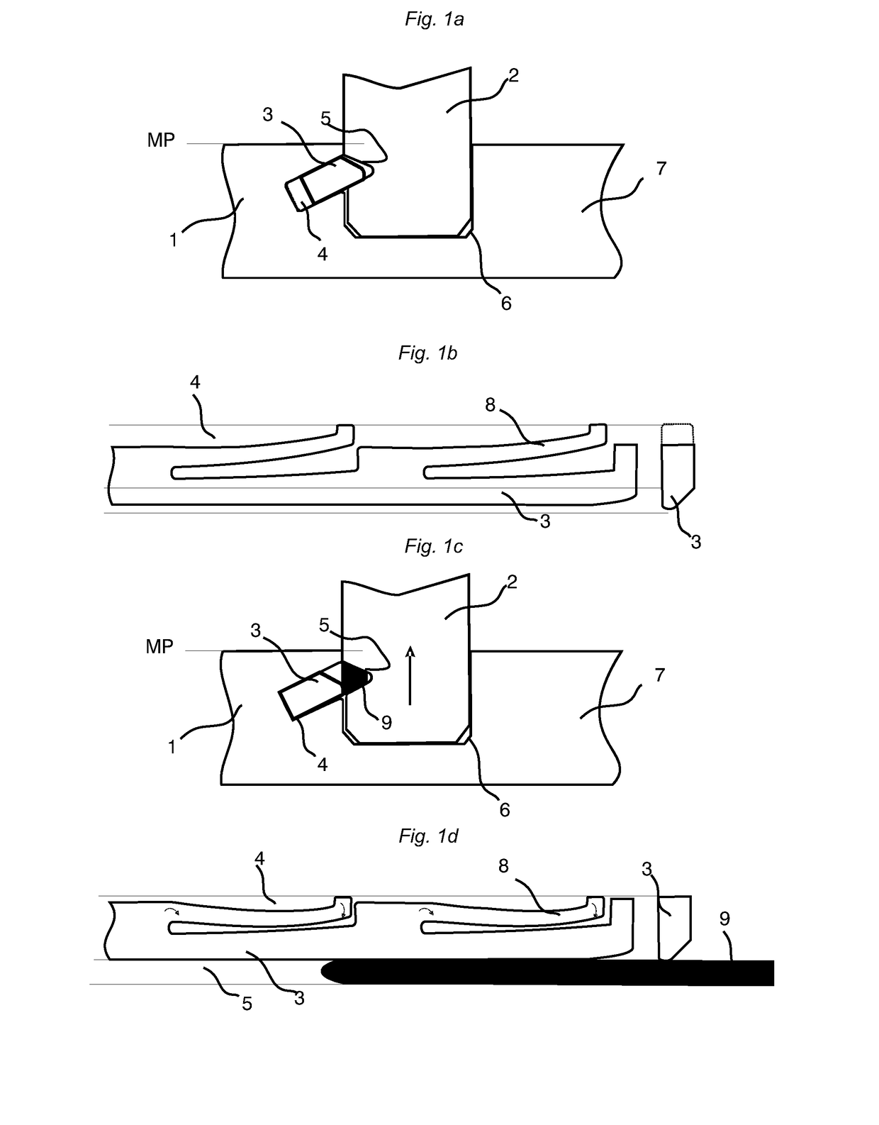
The main problem with such disassembly is that the rod shaped stick 9 must be turned in a correct position and must be inserted precisely into the tongue groove 5.
A disassembly is not possible if the rod shaped stick is inserted into the insertion groove 4.

Method used


Image

  • Mechanical locking system for building panels
  • Mechanical locking system for building panels
  • Mechanical locking system for building panels

Examples


Embodiment Construction

[0052]To facilitate understanding, several locking systems in the figures are shown schematically. It should be emphasised that improved or different functions can be achieved using combinations of the preferred embodiments.

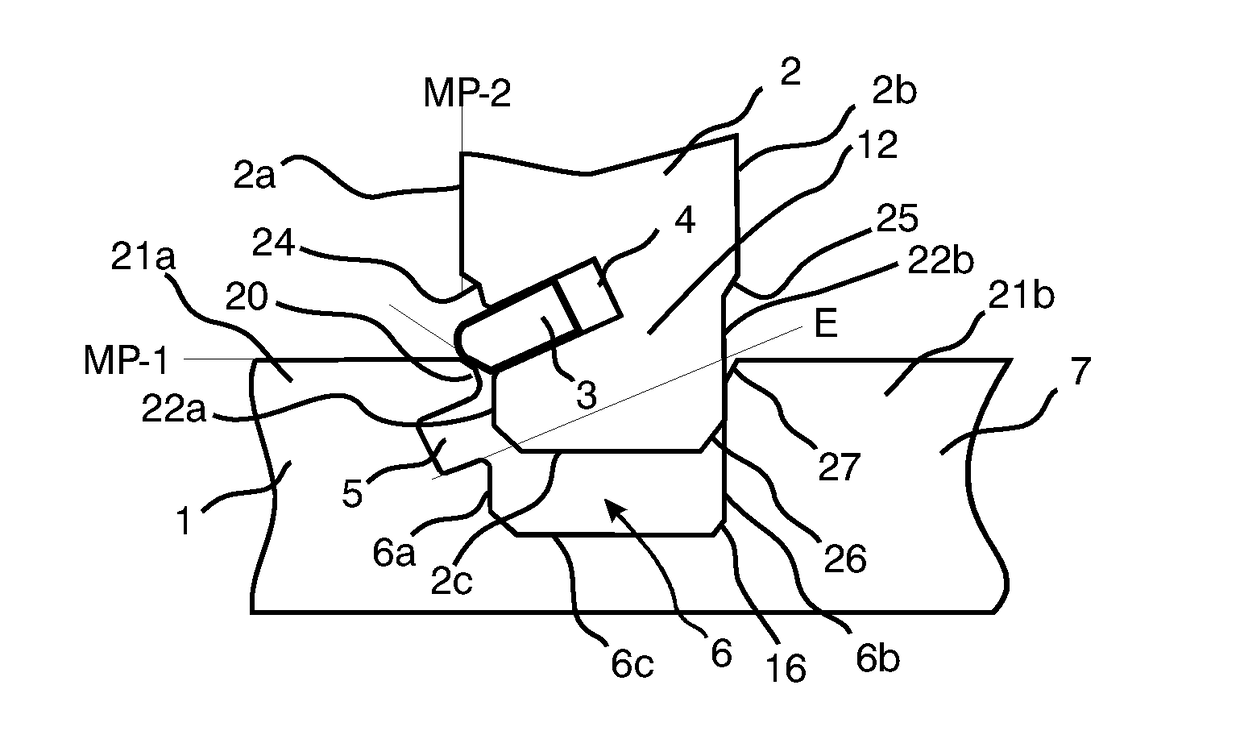
[0053]FIGS. 2a-d illustrate a first panel 1 and a second panel 2 which are connected to each other in accordance with an embodiment. The first panel 1 comprises a core groove 6 which is arranged in an upper side 1b of the first panel 1. The core groove 6 comprises two opposing side walls 6a, 6b and a bottom wall 6c. The opposing side walls 6a, 6b are parallel. The second panel 2 comprises a panel edge 12 which in a locked position of the panels 1, 2 is arranged in the core groove 6. More specifically, a portion of a lower side 2a, a portion of an upper side 2b, and a side edge 2c of the second panel 2 are arranged in the core groove 6. The panels 1, 2 may be locked to each other by means of a separate and flexible tongue 3.

[0054]FIG. 2a shows a top view of the fl...


PUM

PropertyMeasurementUnit
angleaaaaaaaaaa
angleaaaaaaaaaa
angleaaaaaaaaaa

Abstract

Panels are shown, which are provided with a mechanical locking system comprising a separate and flexible tongue allowing connection with a snap action. An outer edge part of the separate flexible tongue comprises a guiding protrusion that facilitates easy disassembly of the panels and that is deformed during locking and / or unlocking.

Description

TECHNICAL FIELD[0001]The disclosure relates to the field of mechanical locking systems for building panels, especially furniture components with mechanical locking systems, which are intended to lock perpendicularly or in parallel to each other.FIELD OF APPLICATION OF THE INVENTION[0002]Embodiments of the present invention are particularly suitable for use in furniture components, which are preferably formed of sheet shaped panels and which are joined mechanically with a locking system integrated with the panel, i.e. mounted at the factory, The following description of known technology, problems of known systems and objects and features of the invention will therefore, as a non restrictive example, be aimed above all at this field of application and in particular at furniture components formed as rectangular or square panels intended to be mechanically joined on one pair of opposite edges perpendicularly or parallel to other adjacent panels.[0003]It should be emphasised that the inv...

Claims


Application Information

Patent Timeline
Patent Type & Authority Applications(United States)
IPC IPC(8): F16B12/12A47B47/00A47B47/04A47B13/02A47B47/02A47B63/00A47B77/00
CPCF16B12/125A47B63/00A47B47/0075A47B47/042A47B13/021A47B47/025A47B77/00F16B12/46A47B2013/022F16B2012/466A47B47/04F16B12/24A47B2088/902
Inventor PERVAN, DARKO
Owner VÄLINGE INNOVATION AB
Learn More