Wireless communication device and wireless communication system

Active Publication Date: 2017-03-16
KOKUSA ELECTRIC CO LTD
View PDF2 Cites 20 Cited by
  • Summary
  • Abstract
  • Description
  • Claims
  • Application Information

AI Technical Summary

Benefits of technology

This patent is about a wireless communication device that can predict communication failures with high accuracy and reduce maintenance load. The device has an imaging unit that takes pictures of a region where the device is located and compares them to a reference image. If there is a significant difference between the two, an alert is generated. The device can also set a monitoring region and predict abnormalities by calculating a similarity index value. This can help to prevent communication failures and improve reliability of communication. The maintenance person can also better handle the causes of the abnormalities.

Problems solved by technology

In this wireless communication system, when deviation in an antenna direction occurs or a building is newly installed between two points, a wireless signal is “unlikely” to arrive linearly (with no reflection), and there is a risk that a communication failure will occur.
However, it is very complicated and large in a work load for a maintenance person to check all photographed images, and in the alert activation based on a comparison of a luminance difference, it responds even to events which are not related to a communication failure such as the weather or a sunshine condition, and an alert is often erroneously activated.
As described above, in the wireless communication device and the wireless communication system according to the related art, when the occurrence of a communication failure is predicted by visual checking, a work of a maintenance person who checks an image is complicated, a load is increased, and when it is determined based on a luminance difference of an image, there is a problem in that an alert is often erroneously activated, for example, due to difference in the weather or the sunshine condition.

Method used


Image

  • Wireless communication device and wireless communication system
  • Wireless communication device and wireless communication system
  • Wireless communication device and wireless communication system

Examples


embodiment

Overview of Embodiment

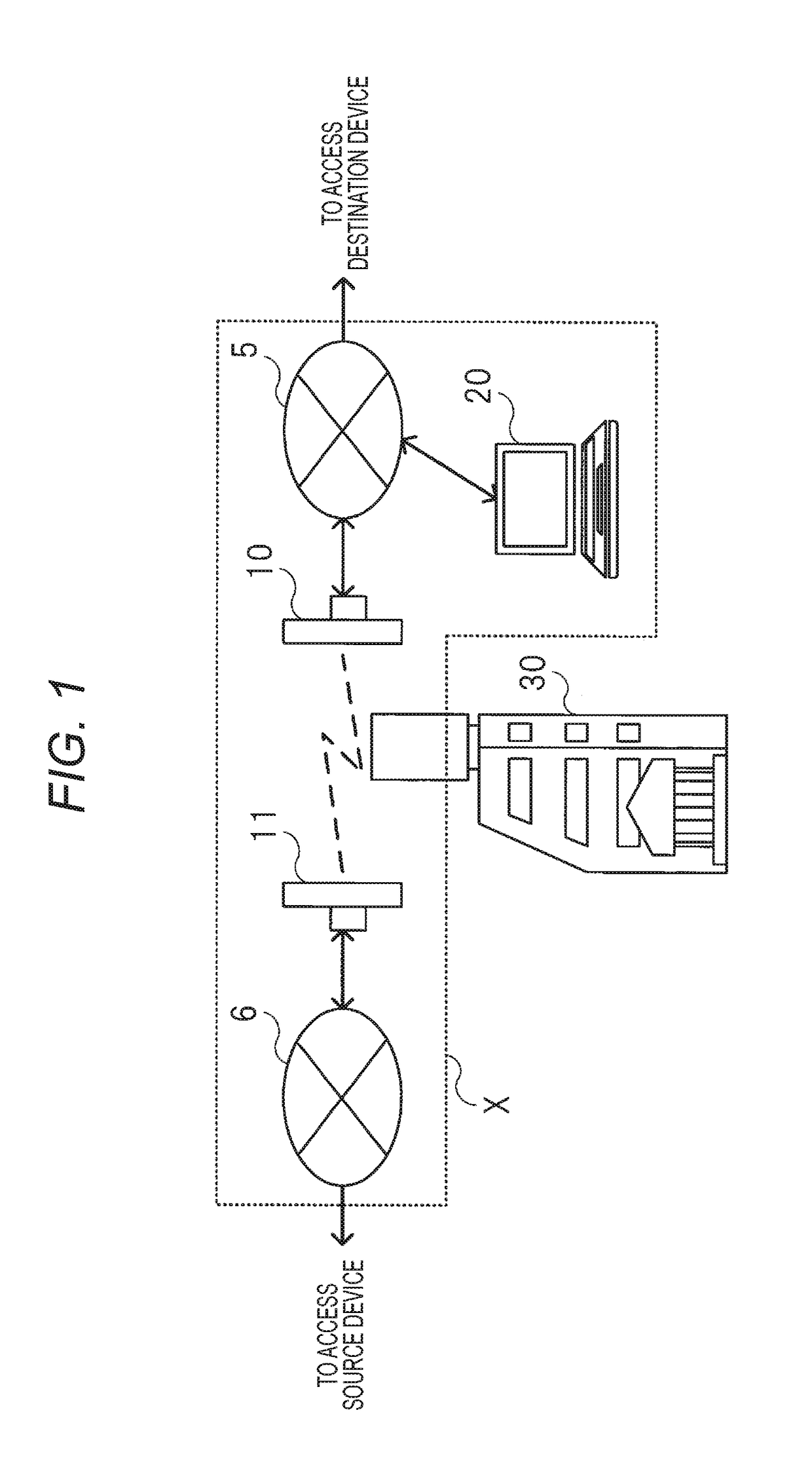
[0036]In a wireless communication system (the present system) according to an embodiment of the present invention, a wireless communication device (the present device) includes an imaging unit having an optical axis which is identical to a radio wave direction of a directional antenna, an image photographed when a condition is good is stored as a reference image, a wireless communication device serving as a communication counterpart and an area around the wireless communication device are photographed, and a control unit compares images photographed at regular intervals with the reference image, calculates a degree of similarity using a template matching technique based on normalized cross-correlation that is hardly influenced by a change in brightness, and activates an alert toward a maintenance terminal when a state in which the degree of similarity is low is continued for a certain period of time. Thus, it is possible to reduce a work burden on a maintenance...


PUM


Abstract

A wireless device includes an imaging unit having an optical axis which is identical to a radio wave direction of a directional antenna, a reference image is stored in a storage unit, a wireless communication device serving as a communication counterpart and an area around the wireless communication device are photographed at regular intervals, and a control unit compares images photographed at regular intervals with a reference image, calculates a degree of similarity through normalized cross-correlation which is hardly influenced by a change in brightness, calculates an index value indicating a state of a region serving as a monitoring target based on a degree of weighted similarity, detects an abnormality when the index value is a specific numerical value or less, and outputs alert information including the photographed image when a state in which the abnormality is detected is continued for a certain period of time.

Description

BACKGROUND[0001]Technical Field[0002]The present invention relates to a wireless communication device and a wireless communication system using a directional antenna, and more particularly, a wireless communication device and a wireless communication system, which are capable of reducing a maintenance load, predicting the occurrence of a communication failure with a high degree of accuracy, and thus improving reliability of communication.[0003]Related Art[0004]In the past, as a fixed wireless access (FWA) wireless communication system having quasi-millimeter to millimeter wavebands, there is a system in which point-to-point (P2P) wireless communication is performed between specific fixed communication devices using an antenna having sharp directivity. Antennas of communication devices constituting a pair are installed to face each other.[0005]In this wireless communication system, when deviation in an antenna direction occurs or a building is newly installed between two points, a wi...

Claims


Application Information

Patent Timeline
IPC IPC(8): H04W24/04G06T7/00H04N7/18
CPCH04W24/04G06T7/0081H04N7/183H04N7/18G06T2207/30232G06T7/277H04W24/08H04W84/14G06T7/11
Inventor IWANAGA, KAZUNARIKOBAYASHI, SHINYASASANAMI, NAOYASU
Owner KOKUSA ELECTRIC CO LTD
Why Eureka
Try Eureka