
Connection member and electricity storage module

a technology of connection member and electricity storage module, which is applied in the direction of cell components, cell component details, batteries, etc., can solve the problems of cumbersome connecting operation and cell degradation, and achieve the effect of simplifying the connecting the external device, and simplifying the connection operation of the detection terminal

Inactive Publication Date: 2017-03-09
AUTONETWORKS TECH LTD +2
View PDF1 Cites 2 Cited by
  • Summary
  • Abstract
  • Description
  • Claims
  • Application Information

AI Technical Summary

Benefits of technology

The present invention provides an electricity storage module with a simplified connection operation for a detection terminal. This is achieved by providing a connection member with a detection terminal portion that can detect the state of the electricity storage element. The connection between the lead terminals and the detection terminal portion is completed by the connection member, reducing the complexity of the connection. Various welding methods can be used, and the risk of electrolytic corrosion in the connecting part is reduced for enhanced electrical connection reliability. The detection terminal portion is insulation-protected, simplifying the connection with an external device.

Problems solved by technology

Here, in the case of connecting the plurality of unit cells in series and / or parallel, there is a problem of causing the degradation of the cells if cell characteristics such as a cell voltage and a cell temperature are non-uniform among the unit cells.
Since the number of connection of the detection terminals increases as the number of the unit cells constituting the battery module increases, there has been a problem that a connecting operation becomes cumbersome.

Method used


Image

  • Connection member and electricity storage module
  • Connection member and electricity storage module
  • Connection member and electricity storage module

Examples


case 15

[0061](Case 15)

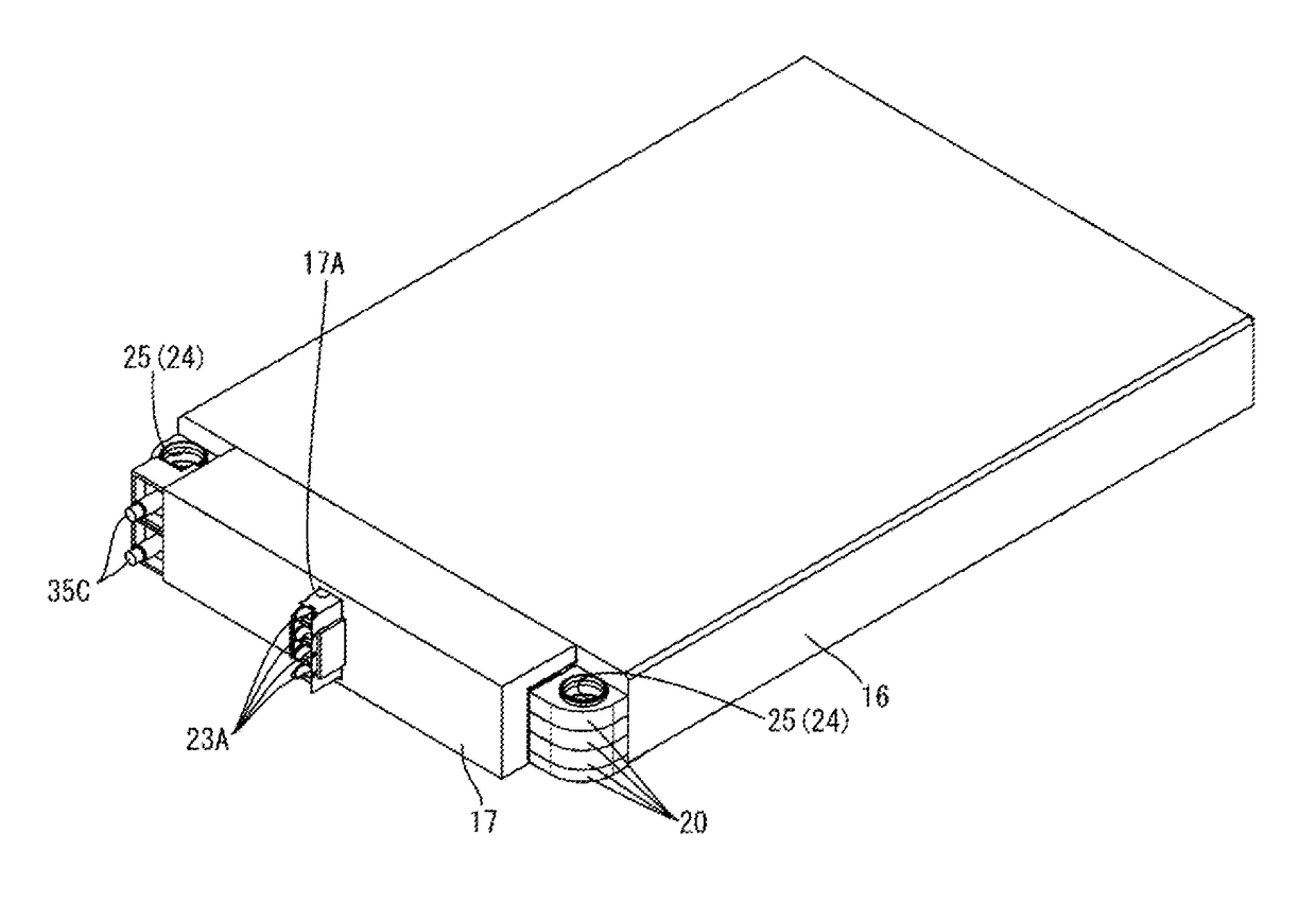
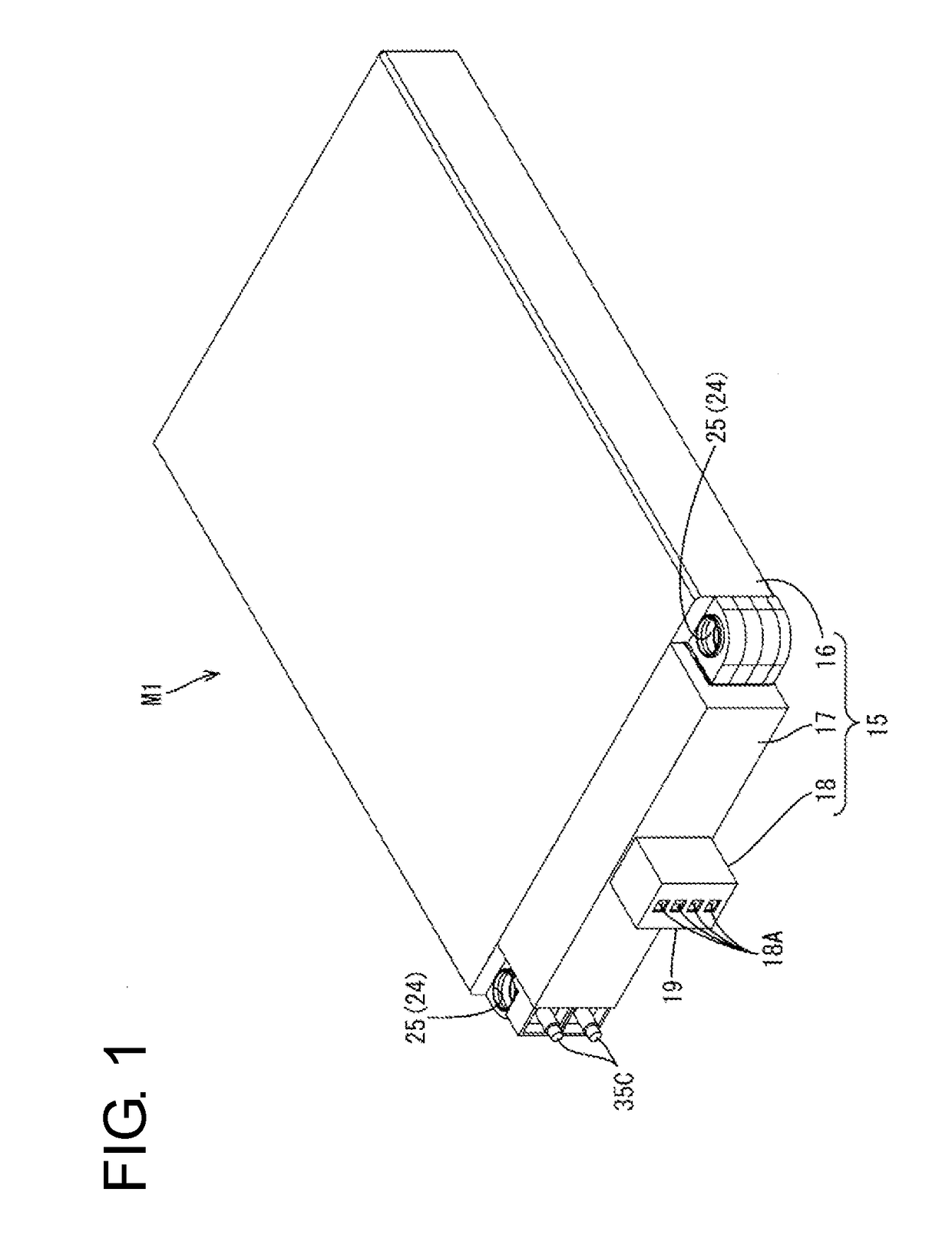
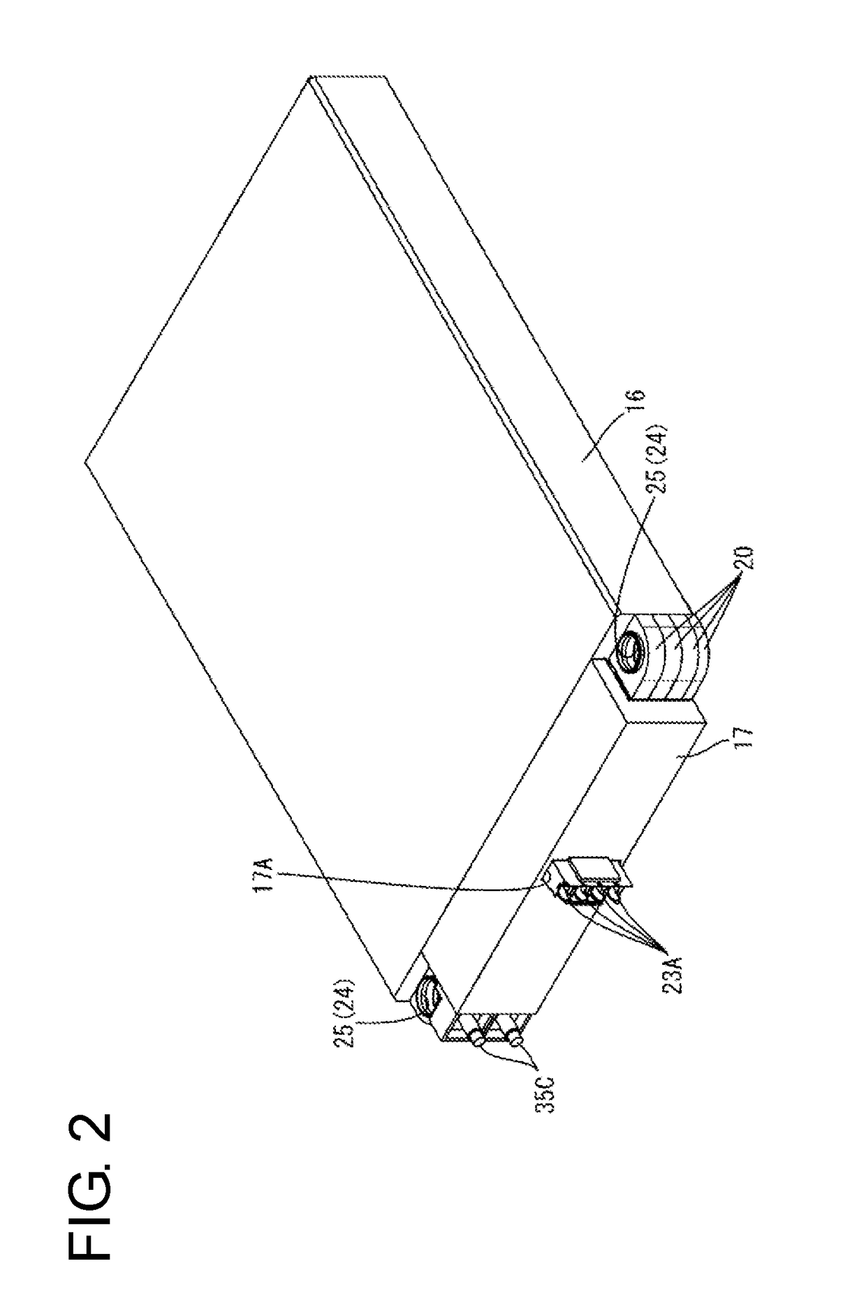
[0062]The case 15 includes a case main body 16 configured to accommodate the electricity storage element group 10 and having an open front side, a holding member cover 17 for covering the holding members 20 arranged at an outer side of an opening of the case main body 16 and a housing 18 mounted on the holding member cover 17.

[0063]The holding member cover 17 covers parts except external connection terminals 35C and fixing portions 24 and terminal accommodating portions 23 formed on the holding members 20.

[0064]As shown in FIG. 2, an insertion portion 17A through which the terminal accommodating portions 23 provided on the holding members 20 are insertable is provided in a center of the holding member cover 17. As shown in FIG. 1, the housing 18 for accommodating the terminal accommodating portions 23 inside is mounted on the insertion portion 17A provided on the holding member cover 17.

[0065]The terminal accommodating portions 23, the housing 18 and detection termina...


PUM

PropertyMeasurementUnit
distanceaaaaaaaaaa
voltageaaaaaaaaaa
temperatureaaaaaaaaaa

Abstract

A connection member (36) for electrically connecting lead terminals (12A, 12B) of electricity storage elements (11) adjacent in a lamination direction out of an electricity storage element group (10) formed by laminating a plurality of electricity storage elements (11) each including a positive-electrode and a negative-electrode lead terminals (12A 12B) projecting in an outward direction from one side edge is provided with a detection terminal portion (50) for detecting a state of the electricity storage element (11). Thus, the connection of the lead terminals (12A, 12B) and the connection of the detection terminal portion (50) are completed by connecting the connection member (36) between the lead terminals (12A, 12B) and an electricity storage module with a simplified connecting operation of the detection terminal portion (50) can be provided.

Description

BACKGROUND[0001]1. Field of the Invention[0002]The present invention relates to a connection member and an electricity storage module.[0003]2. Description of the Related Art[0004]In a battery module for electric vehicle or hybrid vehicle, a plurality of unit cells each having positive and negative electrode terminals are arranged side by side. In such a battery module, the plurality of unit cells are connected in series and / or parallel by connecting the electrode terminals of adjacent unit cells by busbars.[0005]Here, in the case of connecting the plurality of unit cells in series and / or parallel, there is a problem of causing the degradation of the cells if cell characteristics such as a cell voltage and a cell temperature are non-uniform among the unit cells.[0006]Accordingly, detection terminals for detecting the voltages, the temperatures and the like of the unit cells are connected in a battery module for vehicle (see, for example, Japanese Unexamined Patent Publication No. 201...

Claims


Application Information

Patent Timeline
Patent Type & Authority Applications(United States)
IPC IPC(8): H01M2/20H01M2/30H01M2/10H01M10/48H01M50/209H01M50/249H01M50/51H01M50/55H01M50/553
CPCH01M2/206H01M10/482H01M2220/20H01M2/1016H01M2/30Y02E60/10H01M50/553H01M50/51H01M50/249H01M50/209H01M50/55
Inventor SHIMIZU, HIROSHIHIRAMITSU, HIROOMI
Owner AUTONETWORKS TECH LTD
Learn More