Selectively attachable bucket handle
a bucket handle and selectable technology, applied in the field of bucket handles, can solve the problems of orientating the wire bail handle in a very difficult position, the type of bucket becomes very heavy and difficult to lift, and the bucket is difficult to move and handle during use, so as to facilitate a stable stacking of the bucket handl
- Summary
- Abstract
- Description
- Claims
- Application Information
AI Technical Summary
Benefits of technology
Problems solved by technology
Method used
Image

Examples
first embodiment
[0053]FIG. 4 is a perspective view of a selectively attachable bucket handle 201 for use in connection with the bucket 100. The bucket handle 201 comprises a first attachment component 202 and a second attachment component 204, each attached to, part of, and / or integral with a handling component 206. The first attachment component 202 and the second attachment component 204 are configured to, in tandem, secure the bucket handle 201 to the bucket 100, such that the handling component 206 extends perpendicularly away from the side of the bucket 100. The first attachment component 202 and the second attachment component 204 also are configured to translate a lifting force applied to the handling component 206 onto the bucket 100.
[0054]The first attachment component 202 and the second attachment component 204 of the bucket handle 201 are structured differently from each other and, therefore, engage the bucket 100 differently relative to each other. The first attachment component 202 is ...
second embodiment
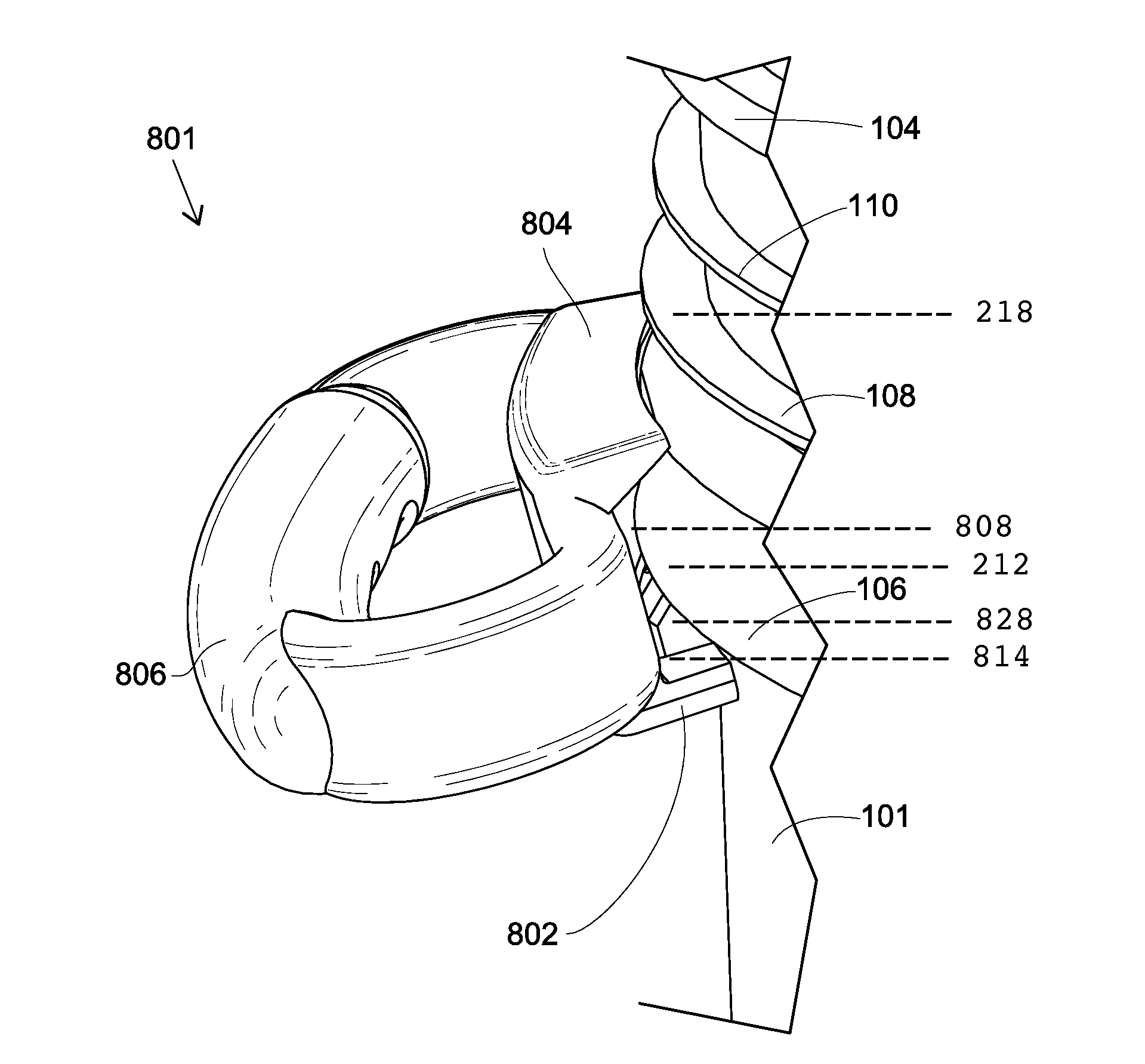
[0061]FIG. 8 is a perspective view of a selectively attachable bucket handle 801. The bucket handle 801 is similar to the bucket handle 201 of FIGS. 4-7 with the following differences. The bucket handle 801 comprises a first attachment component 802 and a second attachment component 804, each integral with a handling component 806. As in the bucket handle 201, the attachment components 802, 804 are attached to the handling component 806 at an attachment region 824. The second attachment component 804 is configured to engage with a second region of the bucket 100 in much the same manner as bucket handle 201. Also as in the bucket handle 201, the second region encompasses a length along the first flange 108 adjacent to the collared skirt 106, or a length between the first flange 108 and the second flange 110, and a corresponding length along the adjacent side wall 101.
[0062]In the embodiment shown in FIG. 8, the rib groove 810 is broader and differently structured than the rib groove ...
third embodiment
[0075]FIG. 14 is a perspective view of a selectively attachable bucket handle 901 for use in connection with the bucket 100. The bucket handle 901 is similar to the bucket handle 801 of FIGS. 8-12 with the following differences. The bucket handle 901 comprises a first attachment component 902 and a second attachment component 904, each integral with a handling component 906. The first attachment component 902 defines a broad rib groove 910, effectively splitting first attachment component 902 into two insert sections 914. The broad rib groove 910 is configured to receive a rib 114 when the first attachment component 902 is engaged with the first region of the bucket 100. The rib groove 910 will allow bucket handle 901 to slide around collared skirt 106 a limited distance.
[0076]The insert sections 914 are structured to have an outer surface similar to, or at least cooperatively similar to, the inner surface of collared skirt 106, whereby when first attachment component 202 in inserte...
PUM
 Abstract
Description
Claims
Application Information
 - R&D
- Intellectual Property
- Life Sciences
- Materials
- Tech Scout
- Unparalleled Data Quality
- Higher Quality Content
- 60% Fewer Hallucinations
Browse by: Latest US Patents, China's latest patents, Technical Efficacy Thesaurus, Application Domain, Technology Topic, Popular Technical Reports.
© 2025 PatSnap. All rights reserved.Legal|Privacy policy|Modern Slavery Act Transparency Statement|Sitemap|About US| Contact US: help@patsnap.com