Printing apparatus
a printing apparatus and printing technology, applied in the field of printing apparatuses, can solve problems such as users' inability to continue holding
- Summary
- Abstract
- Description
- Claims
- Application Information
AI Technical Summary
Benefits of technology
Problems solved by technology
Method used
Image
Examples
first embodiment
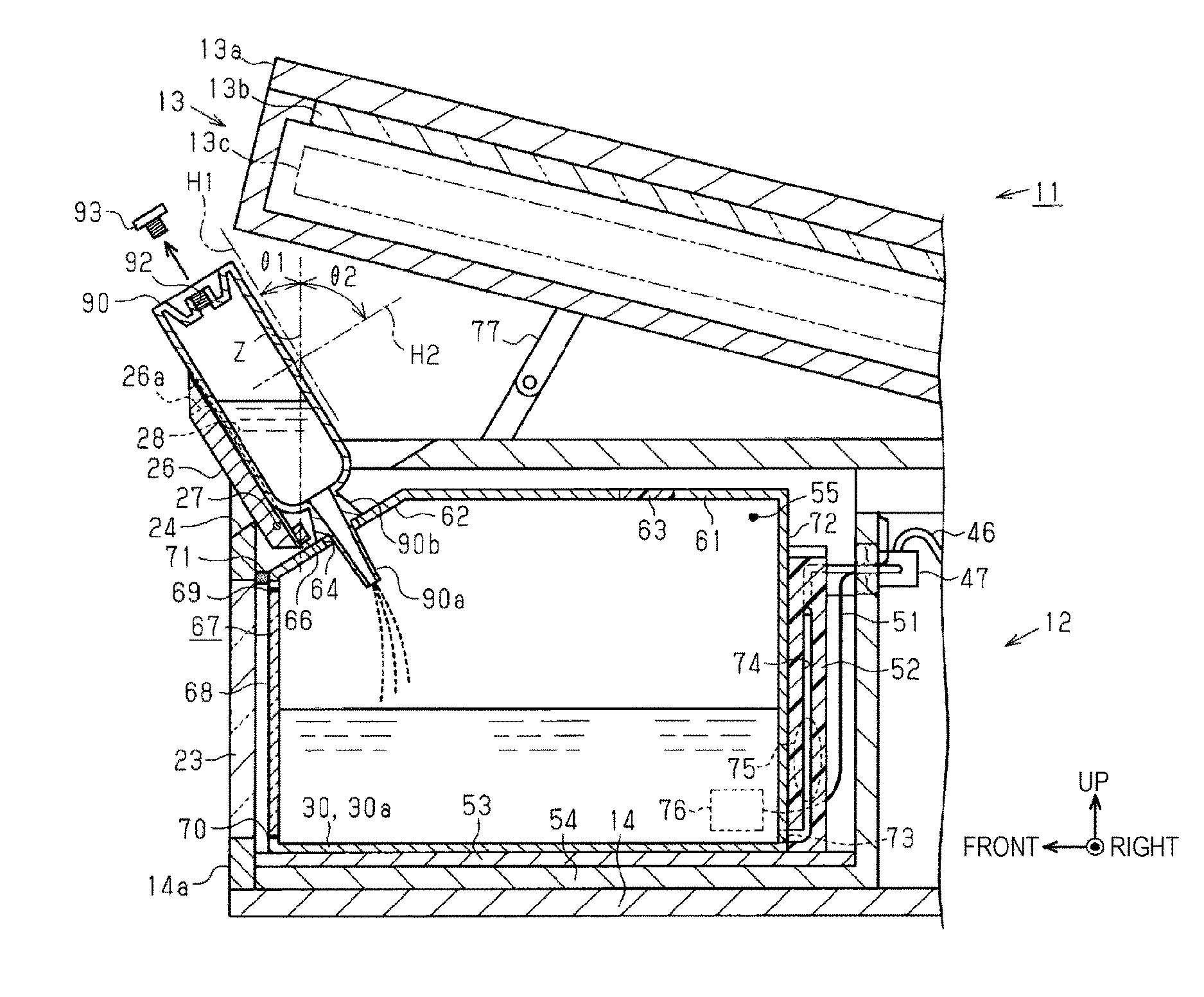
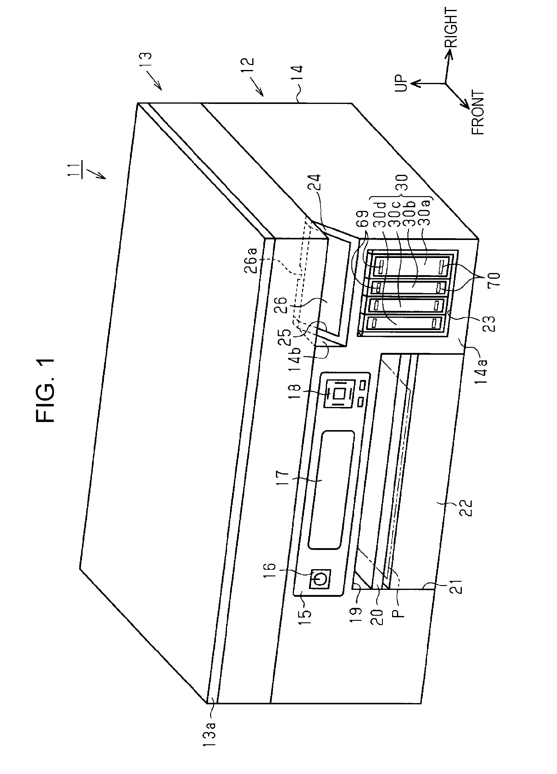
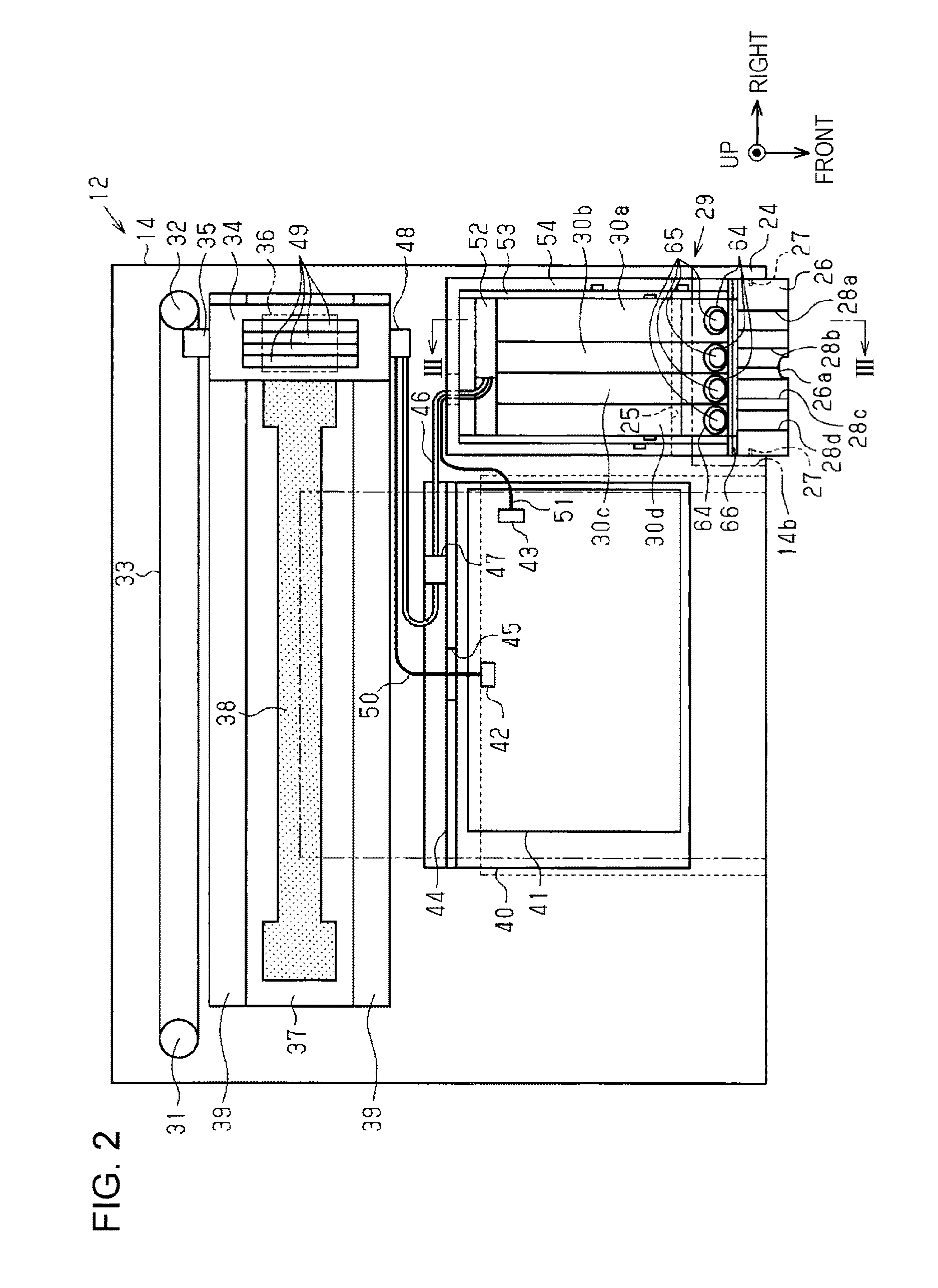
[0037]Hereinafter, a multifunction machine which includes a printing apparatus will be described in detail with reference to the drawings. For example, a printing apparatus of the present embodiment includes an ink jet type of a printer that performs printing by ink which is an example of liquid injected onto paper which is an example of a medium. In addition, the printer is a so called serial type of a printer that performs the printing by moving a liquid ejection head that functions as a printing unit in a main scanning direction intersecting with a transport direction of the paper. Hereinafter, a direction along a transport direction of the paper is referred to as “a longitudinal direction”, a main scanning direction in which the printing unit moves at the time of the printing is referred to as “a lateral direction”, and thus a vertical direction along the gravity direction is referred to as “an upper and lower direction”.
[0038]As illustrated in FIG. 1, the multifunction machine ...
second embodiment
[0082]Next, a printing apparatus 12 of the second embodiment will be described. In the printing apparatus 12 of the present embodiment, a portion of the configuration of an ink bottle being a liquid pouring member and the configuration of the engaging mechanism that engages with the cover member 26 is different from the construction of the first embodiment and other configurations are substantially the same as the first embodiment. For this reason, hereinafter, the configurations that are different from the first embodiment will be described, the other configurations has the same reference numerals and a redundant description is omitted.
[0083]As illustrated in FIG. 5, in the present embodiment different from the first embodiment, an engaging member 66 having a rod shape that extends toward the lateral direction in parallel with a rotating shaft 27 is not provided in the position between the rotating shaft 27 in the position being a rear side of the cover member 26 being the closing ...
third embodiment
[0093]Next, a printing apparatus 12 of the third embodiment will be described. In the printing apparatus 12 of the present embodiment, a portion of the configuration of an ink bottle being a liquid pouring member and the configuration of the engaging mechanism that engages with the cover member 26 is different from the construction of the first embodiment and other configurations are substantially the same as the first embodiment. For this reason, hereinafter, the configurations that are different from the first embodiment will be described, the other configurations has the same reference numerals and a redundant description is omitted.
[0094]As illustrated in FIG. 7, in the present embodiment different from the first embodiment, an engaging member 66 having a rod shape that extends toward the lateral direction in parallel with a rotating shaft 27 is not provided in the position a rear side of the cover member 26 being the closing position in the inside of a casing 14. Instead of thi...
PUM
 Abstract
Description
Claims
Application Information
 - R&D
- Intellectual Property
- Life Sciences
- Materials
- Tech Scout
- Unparalleled Data Quality
- Higher Quality Content
- 60% Fewer Hallucinations
Browse by: Latest US Patents, China's latest patents, Technical Efficacy Thesaurus, Application Domain, Technology Topic, Popular Technical Reports.
© 2025 PatSnap. All rights reserved.Legal|Privacy policy|Modern Slavery Act Transparency Statement|Sitemap|About US| Contact US: help@patsnap.com


