Motor control device capable of measuring temperature of rotor and motor provided therewith

a technology of rotor and temperature, which is applied in the direction of electric motor control, heat measurement, instruments, etc., can solve the problems of affecting the machining quality of the machine tool, the output of the motor following the same command may not be stable, and the estimated temperature of the rotor is not correct, so as to achieve easy and accurate estimation

Inactive Publication Date: 2017-02-02
FANUC LTD
View PDF3 Cites 2 Cited by
  • Summary
  • Abstract
  • Description
  • Claims
  • Application Information

AI Technical Summary

Benefits of technology

The present invention is about a device for controlling the motor that can accurately estimate the temperature of the rotor. It also includes a motor that is provided with this device. This makes it easy to control the motor and prevent damage caused by high temperatures.

Problems solved by technology

In a machine tool which drives a tool by a rotor of a motor, there is a risk that the change in output of the motor in accordance with the temperature change of the rotor may influence the machining quality of the machine tool.
However, if the temperature estimation device described in Japanese Patent Application Laid-open No. 2008-170354 is applied to a motor, the following problem arises.
Accordingly, even if the temperature of the rotor is estimated based on the change in strength of the signal generated by the signal generating means by the temperature estimation device described in Japanese Patent Application Laid-open No. 2008-170354, the estimated temperature of the rotor is not correct.
Therefore, in the temperature estimation device described in Japanese Patent Application Laid-open No. 2008-170354, the temperature of the rotor is not correct, and therefore the output of the motor following the same command may not be stable.
Further, on considering accurately measuring the temperature of a rotor by a different method, it is difficult to directly contact the rotating rotor with a thermometer because the rotor is a rotating body.
However, it is necessary to separately install the infrared temperature measurement device to the motor, and consequently the cost will greatly increase.
Further, there is the problem that only the surface temperature of an object to be measured can be measured by the infrared radiation.

Method used


Image

  • Motor control device capable of measuring temperature of rotor and motor provided therewith
  • Motor control device capable of measuring temperature of rotor and motor provided therewith
  • Motor control device capable of measuring temperature of rotor and motor provided therewith

Examples


Embodiment Construction

[0021]Hereinafter, embodiments of the present invention will be described referring to the drawings. The same reference numerals for the same or corresponding constitutional elements are used over the drawings, with the meaning that these constitutional elements have the same function. Further, the scale of the drawings showing the constitutional elements of the illustrated embodiments has appropriately been adjusted so as to facilitate the understanding of the present inventions.

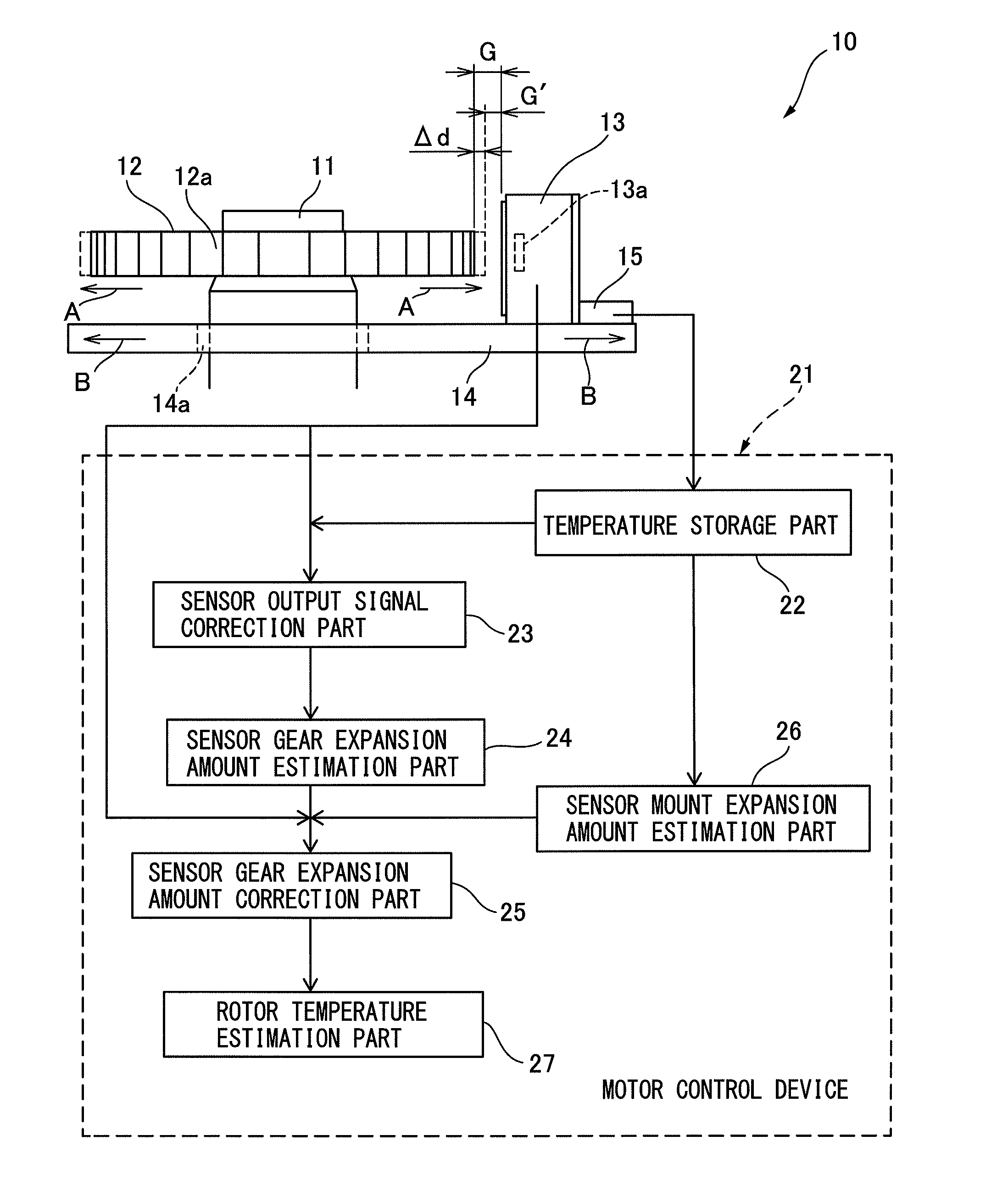
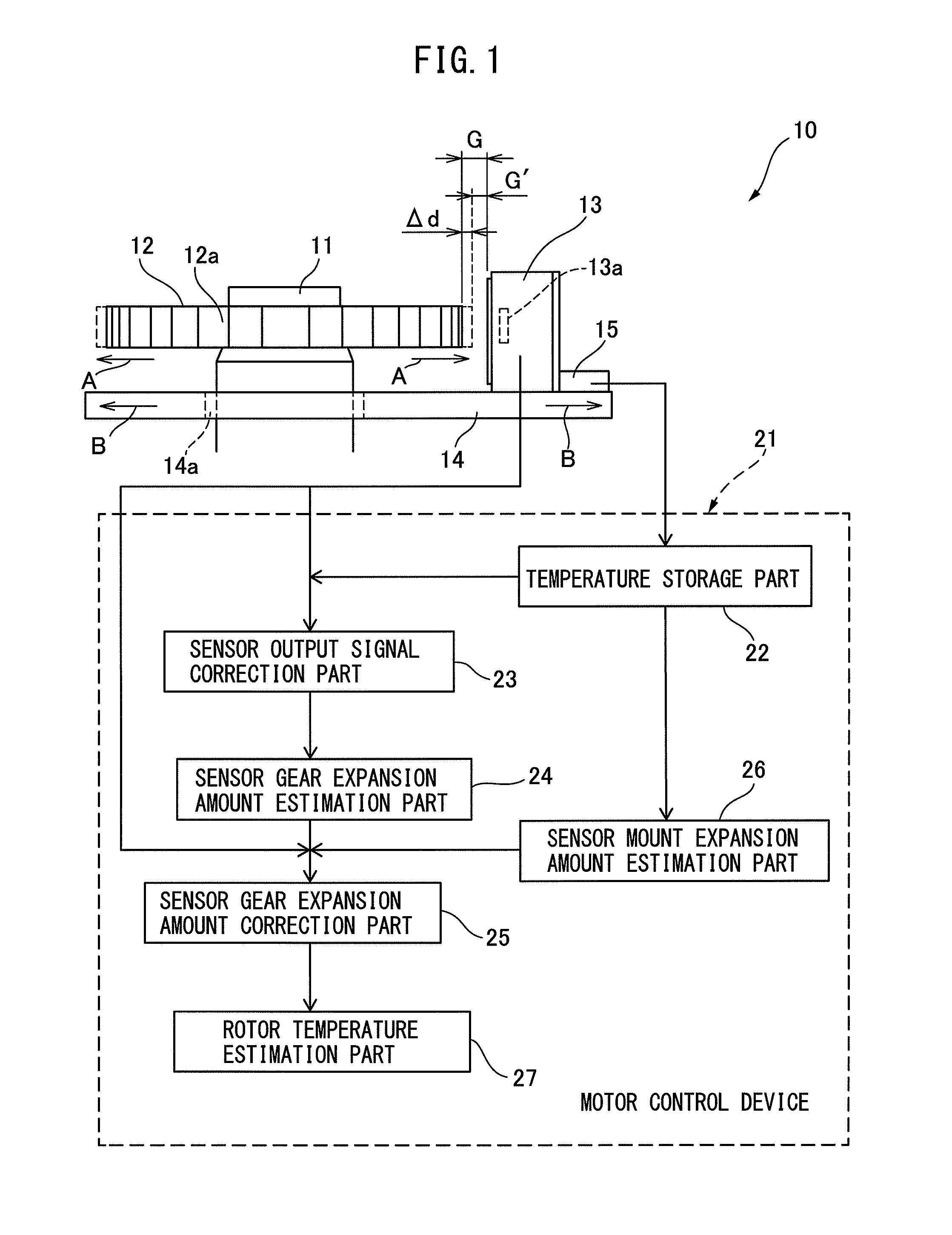
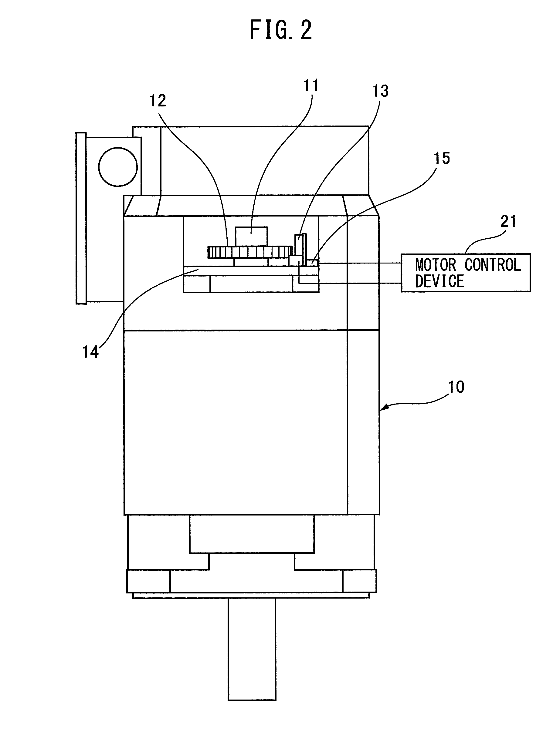
[0022]FIG. 1 is a block diagram schematically illustrating the motor control device according to an embodiment of the present invention. FIG. 2 is a front view of the motor which is controlled by the motor control device illustrated in FIG. 1.

[0023]With reference to FIGS. 1 and 2, a motor 10 of the present embodiment comprises a sensor gear 12 mounted on a rotor 11 of the motor 10, a magnetic sensor 13 which detects the presence / absence of each of a plurality of teeth 12a provided successively at predetermi...


PUM


Abstract

The motor control device of the present invention comprises a sensor gear expansion amount estimation part which estimates the amount of expansion of a sensor gear, a sensor mount expansion amount estimation part which estimates the amount of expansion of a sensor mount, a sensor gear expansion amount correction part which corrects the estimated amount of expansion of the sensor gear, and a rotor temperature estimation part which estimates the temperature of the rotor based on the corrected sensor gear expansion amount of the sensor gear.

Description

BACKGROUND OF THE INVENTION[0001]1. Field of the Invention[0002]The present invention is related to a motor control device which controls a motor while monitoring the temperature thereof, and a motor provided with the motor control device.[0003]2. Related Art[0004]When a motor is operated, the temperature of the rotor of the motor increases to a certain temperature. While the temperature of the rotor increases in this way, even if the command given to the motor is the same, the output of the motor may change. In a machine tool which drives a tool by a rotor of a motor, there is a risk that the change in output of the motor in accordance with the temperature change of the rotor may influence the machining quality of the machine tool. Therefore, technology for estimating the temperature of the rotor in a motor of a machine tool is being investigated. Namely, it is capable of controlling a motor based on the estimated temperature of the rotor so that the output of the motor is stable w...

Claims


Application Information

Patent Timeline
Patent Type & Authority Applications(United States)
IPC IPC(8): H02P29/60H02K11/25
CPCH02K11/25H02P29/60G01B7/24G01K7/22H02K11/20H02K11/215H02P29/66
Inventor YUKAWA, FUMITO
Owner FANUC LTD
Why Eureka
Try Eureka