Light-Emitting Element, Light-Emitting Device, Electronic Device, Lighting Device, and Lighting System
a technology of light-emitting elements and electronic devices, applied in the field of light-emitting elements, can solve the problems that the light-emitting element that emits blue light has not yet been put into practical use, and achieve the effect of high efficiency and energy saving
- Summary
- Abstract
- Description
- Claims
- Application Information
AI Technical Summary
Benefits of technology
Problems solved by technology
Method used
Image
Examples
embodiment 1
[0082]In this embodiment, a mechanism of occurrence of TTA (triplet-triplet annihilation) in an EL layer of a light-emitting element is described.
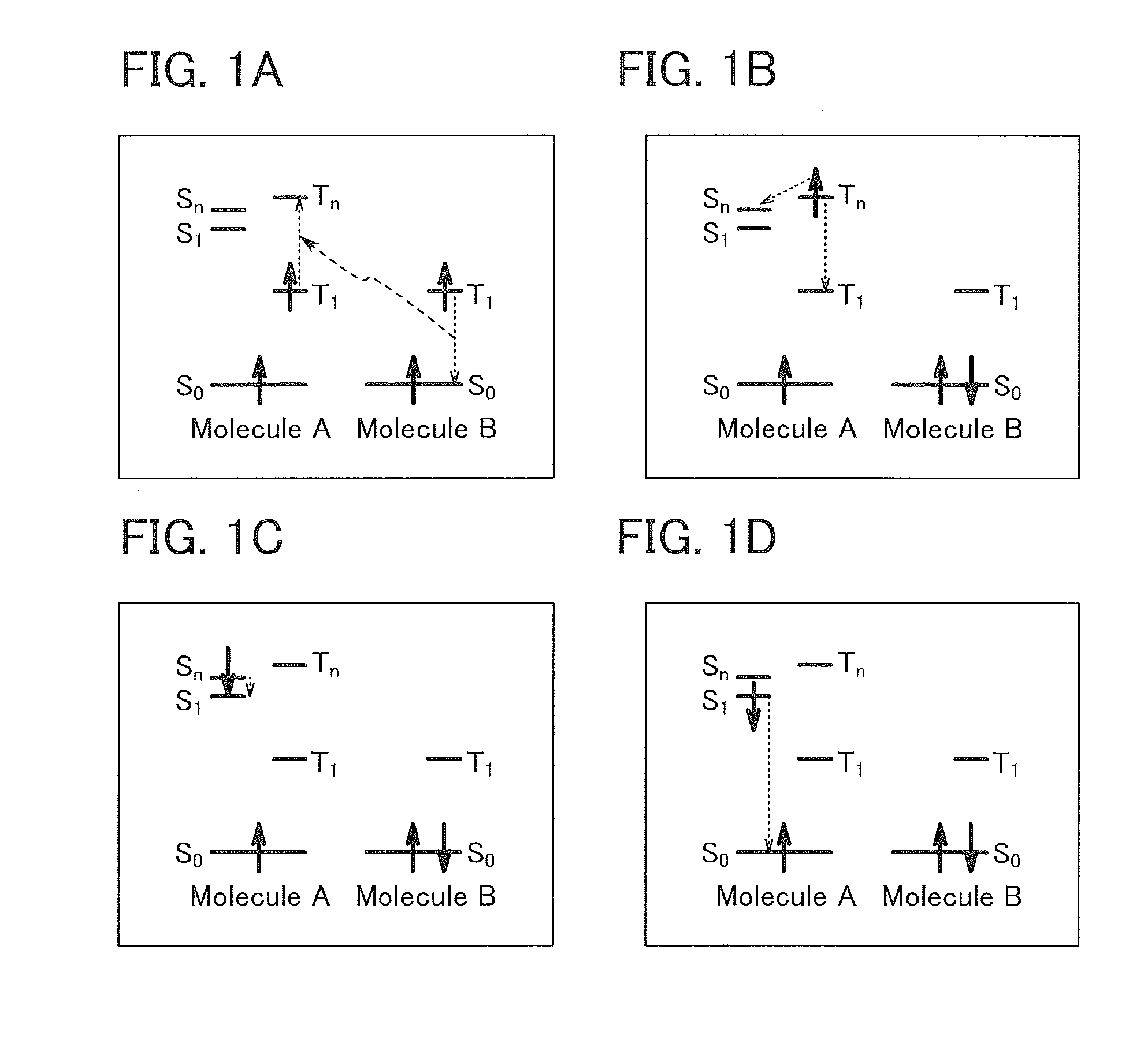
[0083]There are various theories on the detail of the mechanism of TTA, and it is not defined clearly. In one embodiment of the present invention, energy transfer shown in schemes in FIGS. 1A to 1D is assumed to occur in TTA.
[0084]First, in the case where triplet excitons of two molecules of the same kind (a molecule A and a molecule B) exist adjacently as shown in FIG. 1A, energy released when the molecule B transits from a T1 level to an S0 level is absorbed by the molecule A, and an electron at the T1 level of the molecule A transits to a Tn level. Thus, it is thought that the vicinity of an energy level that is higher than the T1 level of the molecule A by the T1 level of the molecule B is the Tn level to which the molecule A can transit.
[0085]Next, as shown in FIG. 1B, the electron transited to the Tn level of the molecule A undergoes...
embodiment 2
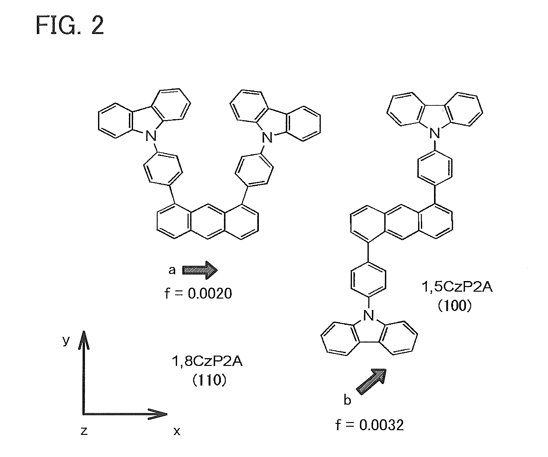
[0111]In this embodiment, an organic compound of one embodiment of the present invention will be described. The organic compound described in this embodiment is an organic compound in which the probability of TTA caused by energy transfer by the Förster mechanism can be increased, as in 1,5CzP2A and 1,8CzP2A described as examples in Embodiment 1.
[0112]The organic compound described in this embodiment has a feature in that a carbazole skeleton is bonded to an anthracene skeleton directly or through an arylene group. The organic compound described in this embodiment is an organic compound having a structure represented by General Formula (G1).
[0113]Note that either of A1 and A2 in General Formula (G1) is a substituent represented by General Formula (G1-1), and the other is hydrogen or another substituent. That is, α2 is bonded to the 5-position or 8-position of the anthracene skeleton in General Formula (G1). In addition, α1 and α2 individually represent a substituted or unsubstituted...
embodiment 3
[0132]In Embodiment 3, a light-emitting element of the present invention will be described with reference to FIGS. 4A and 4B.
[0133]In the light-emitting element described in this embodiment, an EL layer 102 including a light-emitting layer 113 is provided between a pair of electrodes (a first electrode (anode) 101 and a second electrode (cathode) 103). The EL layer 102 includes, in addition to the light-emitting layer 113, a hole-injection layer 111, a hole-transport layer 112, an electron-transport layer 114, an electron-injection layer 115, and the like.
[0134]When a voltage is applied to the light-emitting element, holes injected from the first electrode 101 side and electrons injected from the second electrode 103 side recombine in the light-emitting layer 113; with energy generated by the recombination, a light-emitting substance such as an organometallic complex that is contained in the light-emitting layer 113 emits light.
[0135]The hole-injection layer 111 in the EL layer 102 ...
PUM
 Abstract
Description
Claims
Application Information
 - R&D
- Intellectual Property
- Life Sciences
- Materials
- Tech Scout
- Unparalleled Data Quality
- Higher Quality Content
- 60% Fewer Hallucinations
Browse by: Latest US Patents, China's latest patents, Technical Efficacy Thesaurus, Application Domain, Technology Topic, Popular Technical Reports.
© 2025 PatSnap. All rights reserved.Legal|Privacy policy|Modern Slavery Act Transparency Statement|Sitemap|About US| Contact US: help@patsnap.com


