Robot controller for robot which sets two objects in combined state

Active Publication Date: 2017-01-12
FANUC LTD
View PDF4 Cites 17 Cited by
  • Summary
  • Abstract
  • Description
  • Claims
  • Application Information

AI Technical Summary

Benefits of technology

The present invention aims to provide a robot controller that can help a robot move an object and another object quickly and stably to set them in a combined state where they are in contact with each other. This will help in achieving a desired outcome.

Problems solved by technology

The force about the axis of rotation may be prone to noise or vibration or take a small value.
It is, therefore, difficult to achieve smooth convergence to the above-mentioned state by rapid rotation based on the force about the predetermined axis of rotation.
When the target force in the direction to press is small, it is more difficult to achieve smooth convergence to the above-mentioned state by rapid rotation based on the force about the predetermined axis of rotation, because of the small force about the predetermined axis of rotation.
In contrast to this, when a given object and a different object are set in a state in which a predetermined portion of the given object and a predetermined portion of the different object are in contact and combined with each other, inserting the given object into the different object does not facilitate convergence to the orientation.
It is, therefore, hard to achieve smooth convergence to the above-mentioned state in a short period of time by rotation based on the force about the predetermined axis of rotation.
Increasing the control gain of the force about the predetermined axis of rotation makes the robot operation unstable and prone to oscillation.
Since the magnitude of the control gain of the force about the predetermined axis of rotation is limited, the velocity of rotation about the predetermined axis of rotation may not be increased considerably.
Since increasing the control gain of the force in the direction to press makes the robot operation unstable and prone to oscillation, the force control gain can be increased only to a certain threshold.
As described earlier, when the given object is rotated relative to the different object about a predetermined axis of rotation, it is difficult to speed up rotation or keep the velocity of rotation high by increasing the force control gain.
It is, in turn, difficult to stably, quickly set the given object and the different object in a state in which these objects are in contact with each other in at least one predetermined direction of translation and in which the forces about at least one predetermined axis of rotation are equilibrated to zero.
As a result, it may take much time to obtain a combined state, or the orientation may move over a target state, leading to a waste of time in convergence to the target state.

Method used


Image

  • Robot controller for robot which sets two objects in combined state
  • Robot controller for robot which sets two objects in combined state
  • Robot controller for robot which sets two objects in combined state

Examples


first embodiment

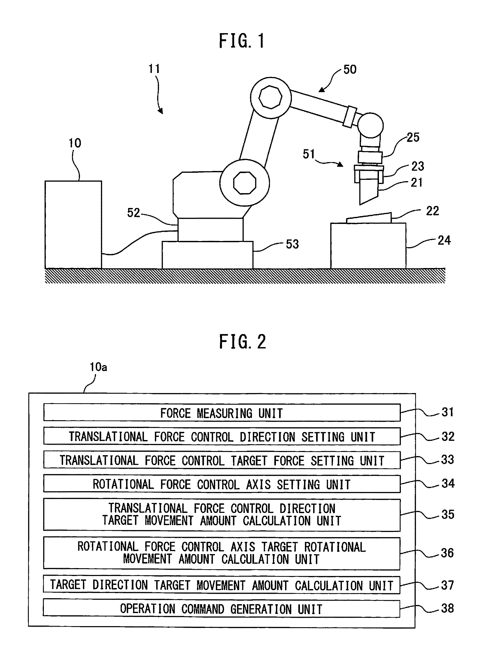
[0078]FIG. 2 is a block diagram functionally illustrating the configuration of a robot controller 10a according to the present invention. The robot controller 10a includes a force measuring unit 31, a translational force control direction setting unit 32, a translational force control target force setting unit 33, a rotational force control axis setting unit 34, a translational force control direction target movement amount calculation unit 35, a rotational force control axis target rotational movement amount calculation unit 36, a target direction target movement amount calculation unit 37, and an operation command generation unit 38, as illustrated as FIG. 2. The robot controller 10 further includes a storage unit and a signal output unit which outputs various signals, although not illustrated.

[0079]The force measuring unit 31 measures a force acting between the given object 21 held on the end effector 51 of the robot 50 and the different object 22. In doing this, a force translat...

fourth embodiment

[0187]FIGS. 18a to 18e are partial enlarged views illustrating an operation for setting the given object 21 and the different object 22 in a combined state by the robot controller 10 according to the present invention. FIG. 18a illustrates the state at the start of movement to set the given object 21 and the different object 22 in a combined state, a predetermined direction independent of the moving operation of the given object 21 is set as a direction of translational force control 61, and an axis which runs in a predetermined direction independent of the moving operation of the given object 21 and passes through a control point for the given object 21 is set as an axis of rotational force control 62. The direction of translational force control of the given object 21 relative to the different object 22 may be changed, instead of a predetermined direction, as in other embodiments. As the given object 21 is translated relative to the different object 22 in the direction of translat...

third embodiment

[0188]Next, the given object 21 is moved to change the contact position for the different object 22, as illustrated as FIG. 18c. At this time, the given object 21 is moved in the direction of translational force control 61 while rotating it about the axis of rotational force control 62 so that the contact position for the different object 22 changes. In the above-mentioned movement, the given object 21 may be moved relative to the different object 22 in a direction of translation, such as a direction perpendicular to the direction of translational force control 61, so that the contact position for the different object 22 changes. As described in conjunction with the robot controller 10 according to the present invention, the given object 21 may be moved about an axis of rotational force control, which is set to pass through a predetermined position specified for the given object 21 or the different object 22, such as the position at which the given object 21 and the different object...


PUM


Abstract

A robot controller which uses a robot to more stably, more rapidly move a given object and a different object relative to each other to set the given object and the different object in a combined state in which portions of the two objects are in contact and combined with each other. The robot controller includes an unit which measures a force acting between two objects, an unit which sets a direction of translational force control, an unit which sets a translational force control target force, an unit which sets an axis of rotational force control, an unit which calculates a target amount of translational force control direction movement, an unit which calculates a target amount of rotational force control axis rotational movement, an unit which calculates a target amount of rotational movement, and an unit which generates an operation command for the robot.

Description

BACKGROUND OF THE INVENTION[0001]1. Field of the Invention[0002]The present invention relates to a robot controller for a robot which controls the force acting between a given object located on the end effector of the robot and a different object to move the given object relative to the different object to set the given object and the different object in a combined state in which a predetermined portion of the given object and a predetermined portion of the different object are in contact and combined with each other.[0003]2. Description of the Related Art[0004]In fitting, two objects are moved relative to each other to fit the shape of a certain portion in one object with that of a certain portion in the other object. The fitting refers herein to fitting a pair of objects having complementary shapes together, i.e., moving two objects to obtain a relationship in which shafts are firmly fitted together or loosely, slidably fitted together in recesses.[0005]It is a common practice to ...

Claims


Application Information

Patent Timeline
IPC IPC(8): B25J9/16B25J13/08
CPCB25J9/1633G05B2219/39505B25J13/085B25J9/10B25J9/1612B25J9/1687
Inventor IWATAKE, TAKAHIRO
Owner FANUC LTD
Why Eureka
Try Eureka